


Board layout and components
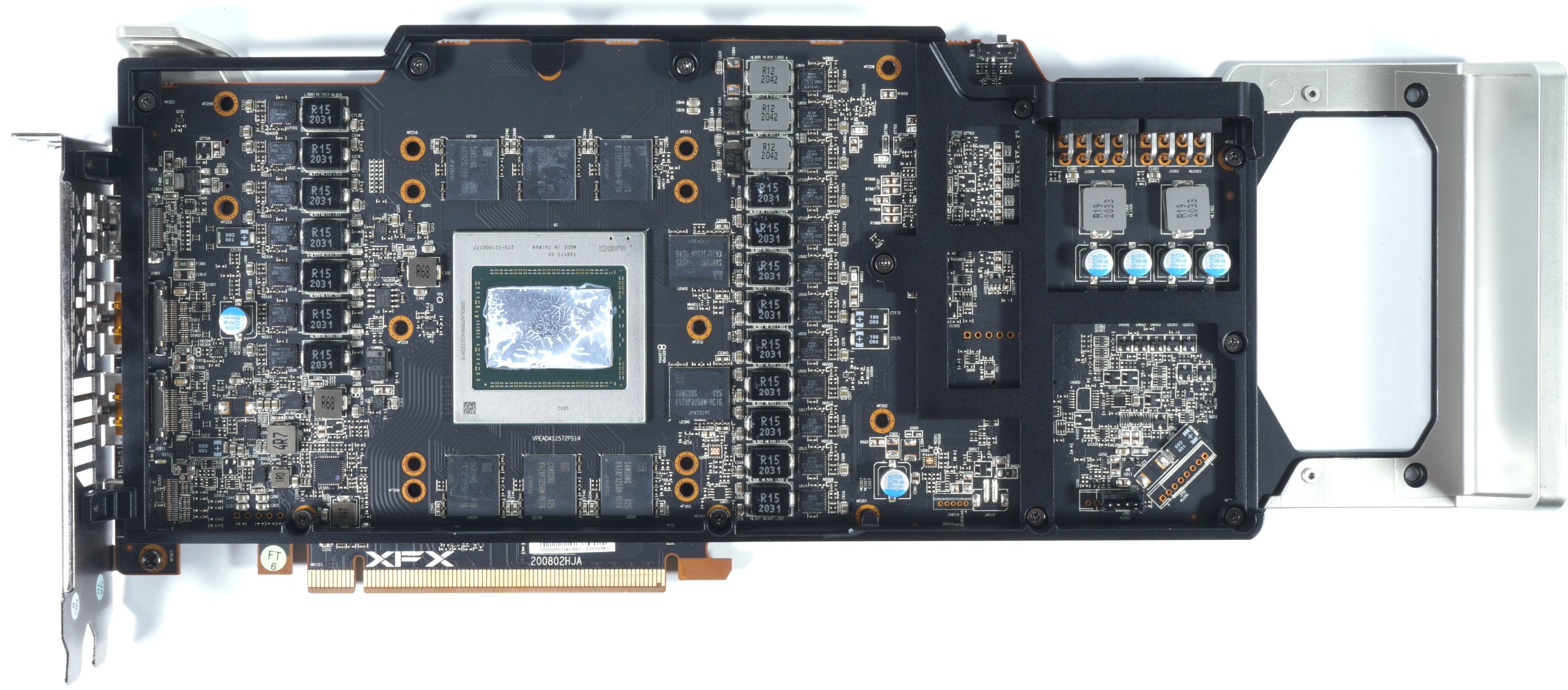
XFX (like AMD) has almost outdone itself with the board. Well equalized hotspots and a very thoughtful design with a very neat input filtering after the two 8-pin connectors, which relies on a proper LC filter (low-pass) and not only on series coils (chokes), should on the one hand mitigate the load peaks on the power supply and on the other hand also increase the stability of the overall system. Nobody really needs annoying HF wave salad.
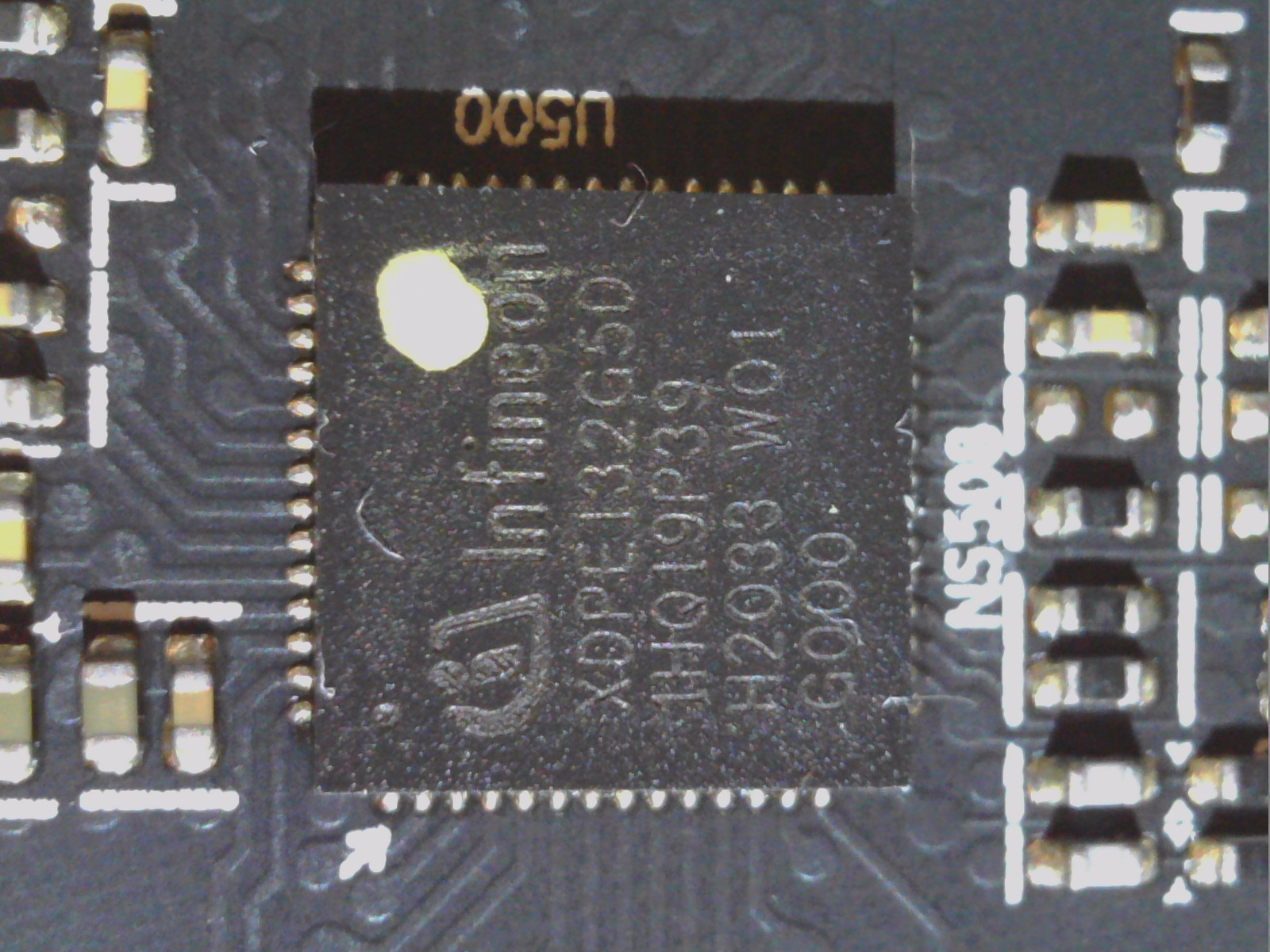
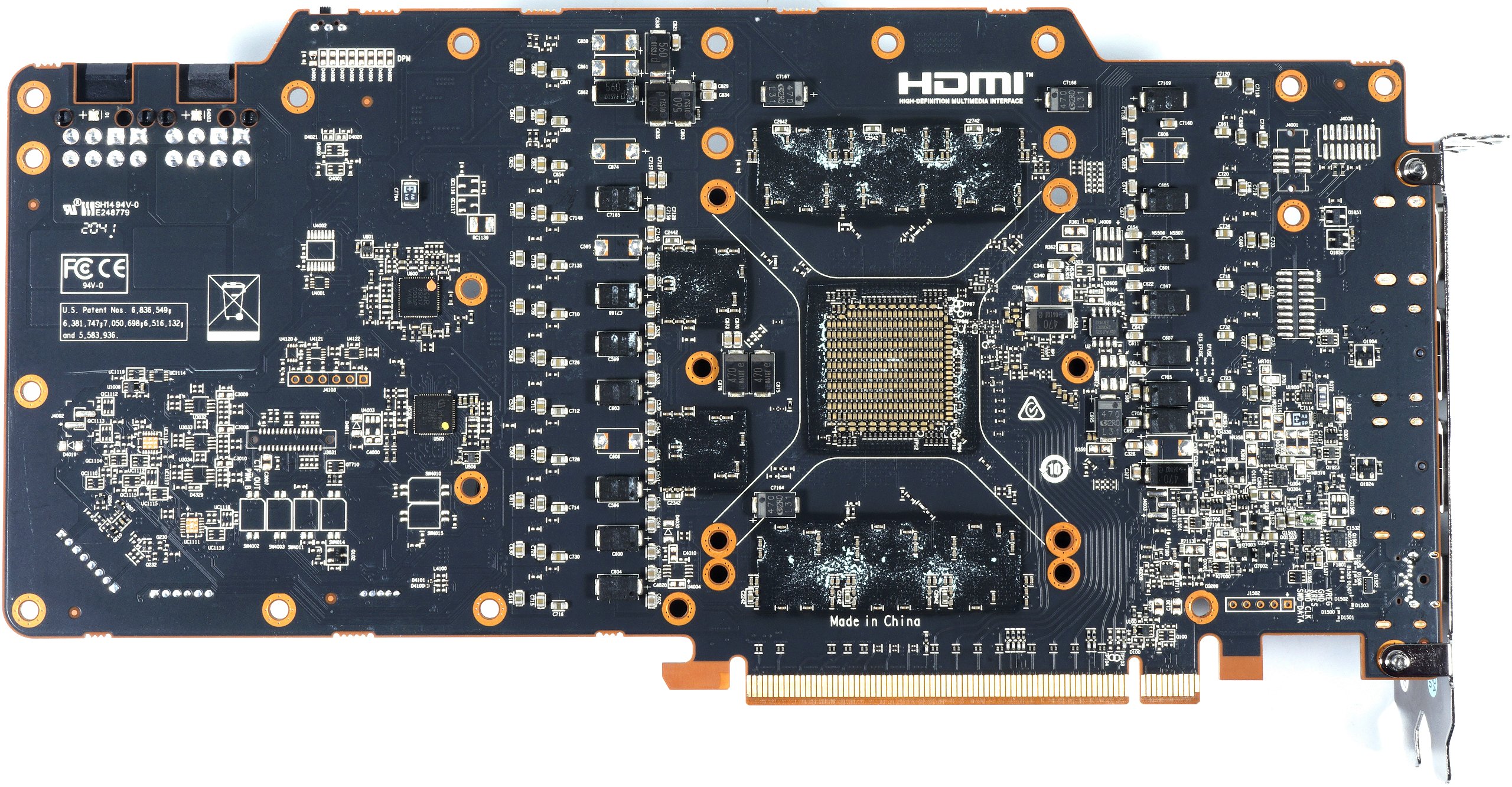
With an XDPE132G5C from Infineon, one relies, like AMD, on a very high-quality PWM controller, which drives the 13 phases for VDDC_GFX in the XFX RX 6800 XT Merc 319 16 GB. For almost all important active components and the coils, XFX relies on the same component selection as AMD’s reference. A correct decision. In the upper right corner we also see the BIOS switch.
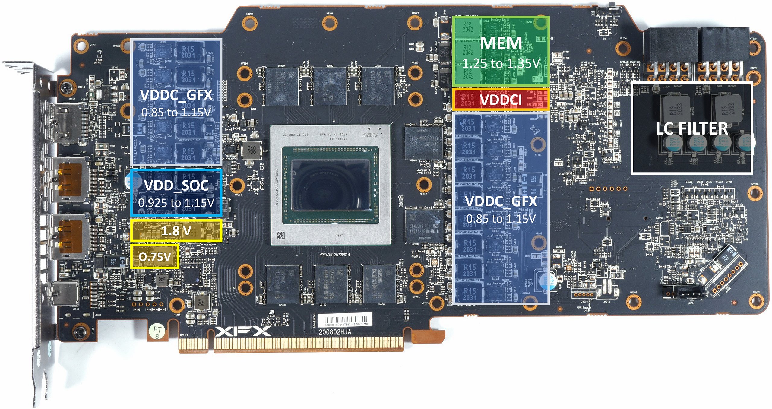
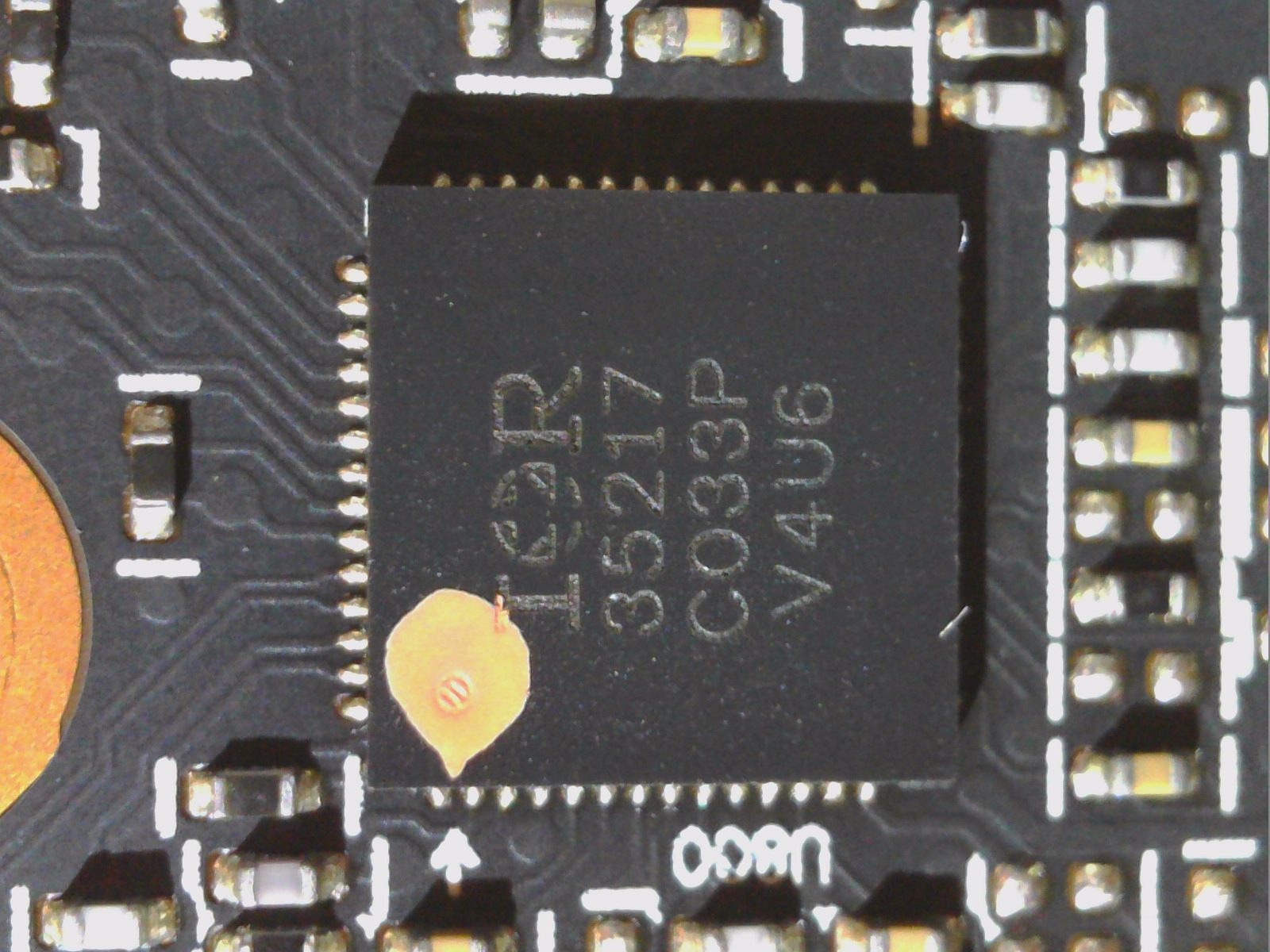
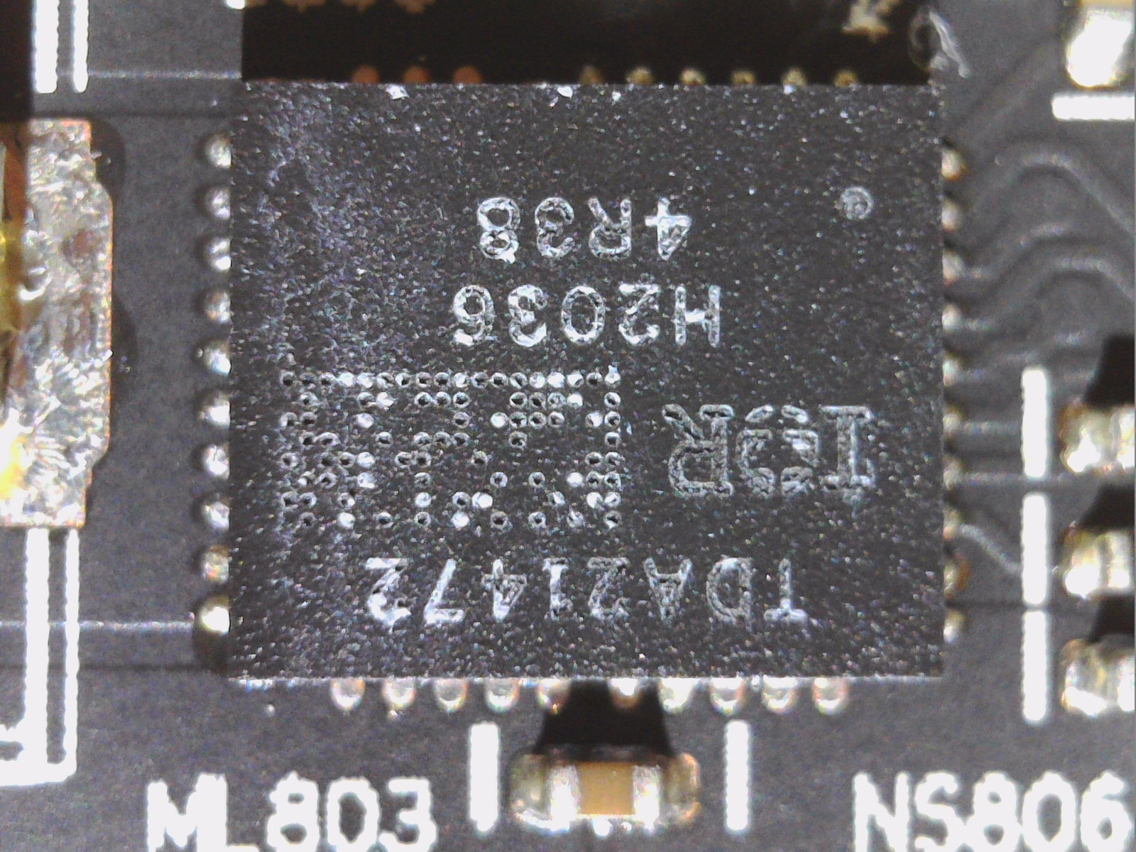
Parallel to this, another IR352717 works for the generation of other partial voltages like 2 phases for VDDC_SOC and even 3 (instead of 2) phases for VDDIO_MEM. In addition, we find another phase for VDDCI, so that in total there are 16 phases for the various main voltages, all of which work with one TDA21472 per phase as a Smart Power Stage, which can supply a maximum of 70A. The TDA21472 includes a synchronous buck-gate driver IC in a Schottky diode co-package, as well as the high-side and low-side MOSFETs. The combination of gate driver and MOSFET (DrMOS) enables higher efficiency at the low output voltages for the GPU.
The internal MOSFET current sensing algorithm with temperature compensation achieves higher current sensing accuracy compared to the best inductor DCR sensing methods. Protection includes cycle-by-cycle overcurrent protection with programmable threshold, VCC/VDRV UVLO protection, phase fault detection, IC temperature detection, and thermal shutdown. The TDA21472 also features automatic bootstrap capacitor refill to prevent over-discharge.
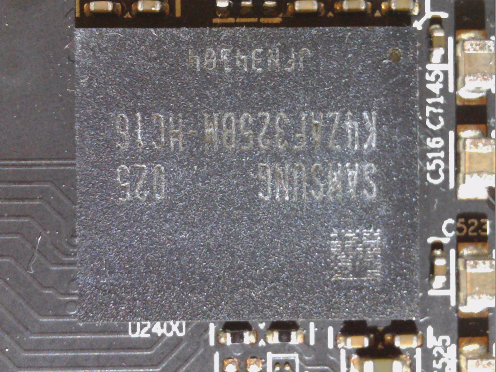
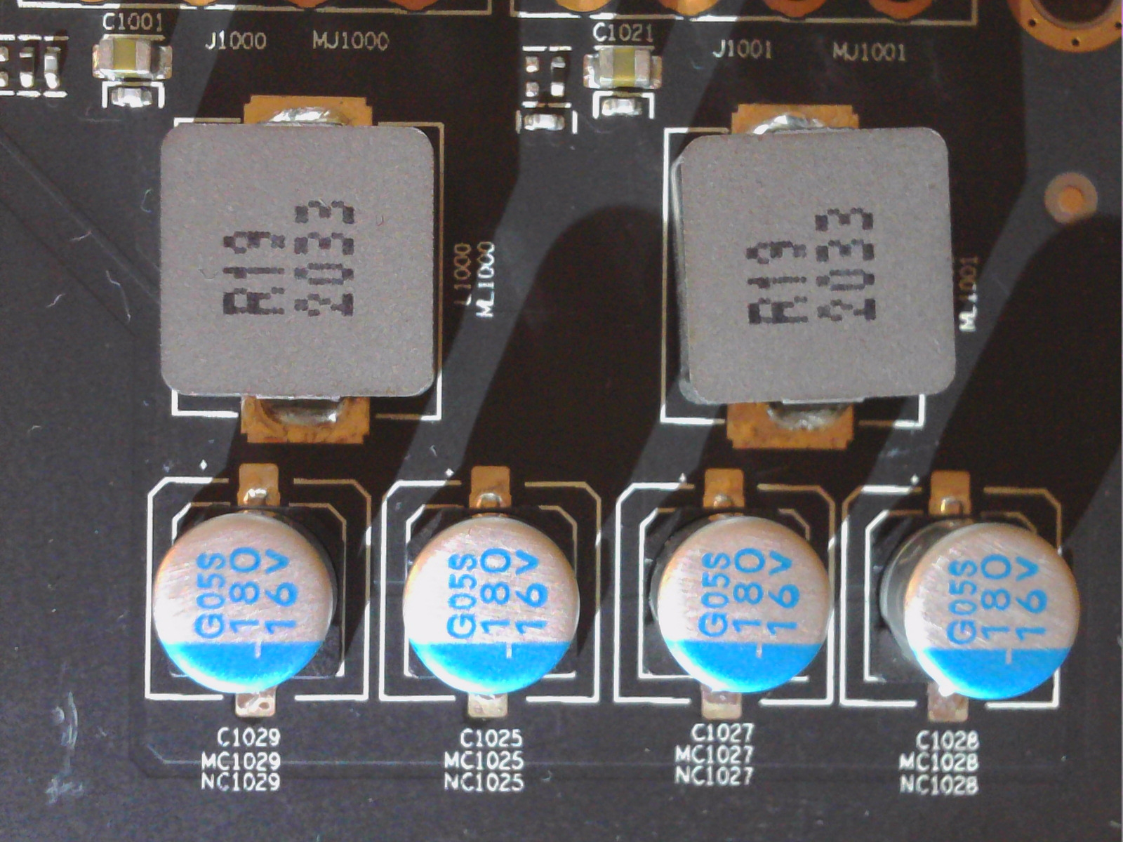
The TDA21472 also features a deep sleep power saving mode that greatly reduces power consumption when the multiphase system enters PS3/PS4 mode. This certainly explains the very low idle load that both new Radeon cards produce. The used coils with 150 mH are quite decent, but sometimes they buzz quite audibly. Sapphire installs a total of 8 GDDR6 memory modules from Samsung with 16 Gbps.
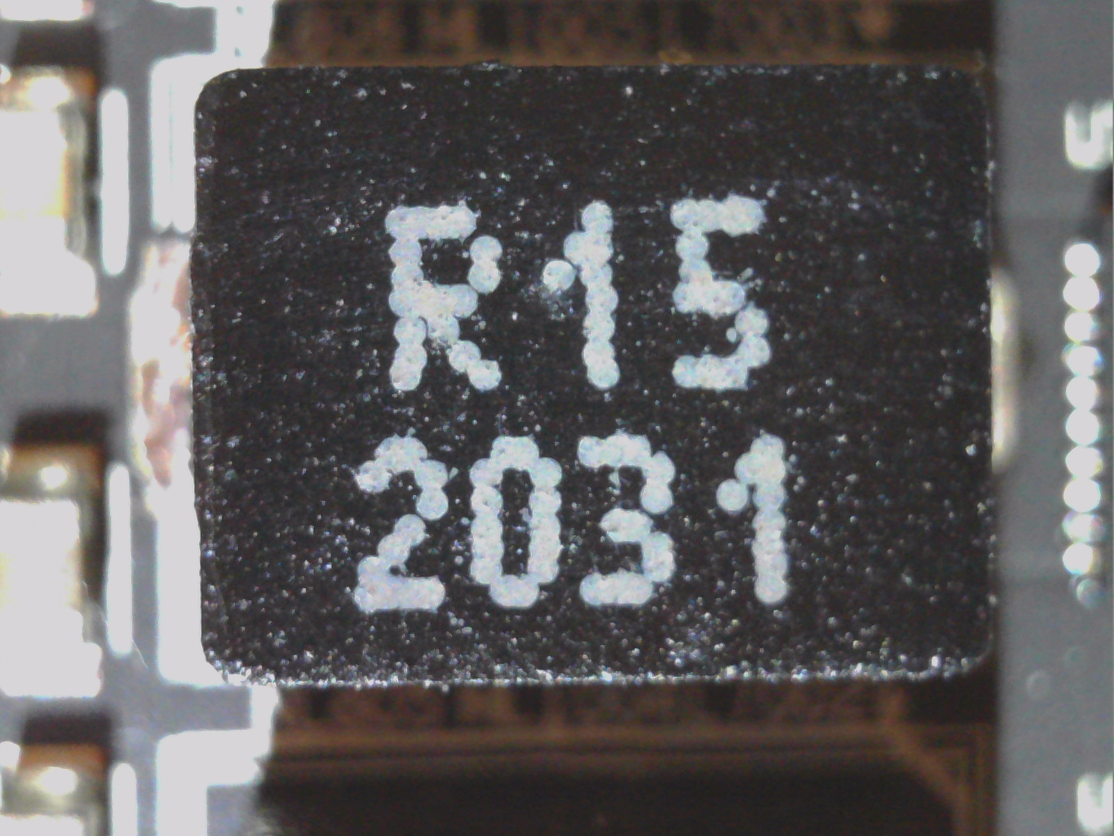
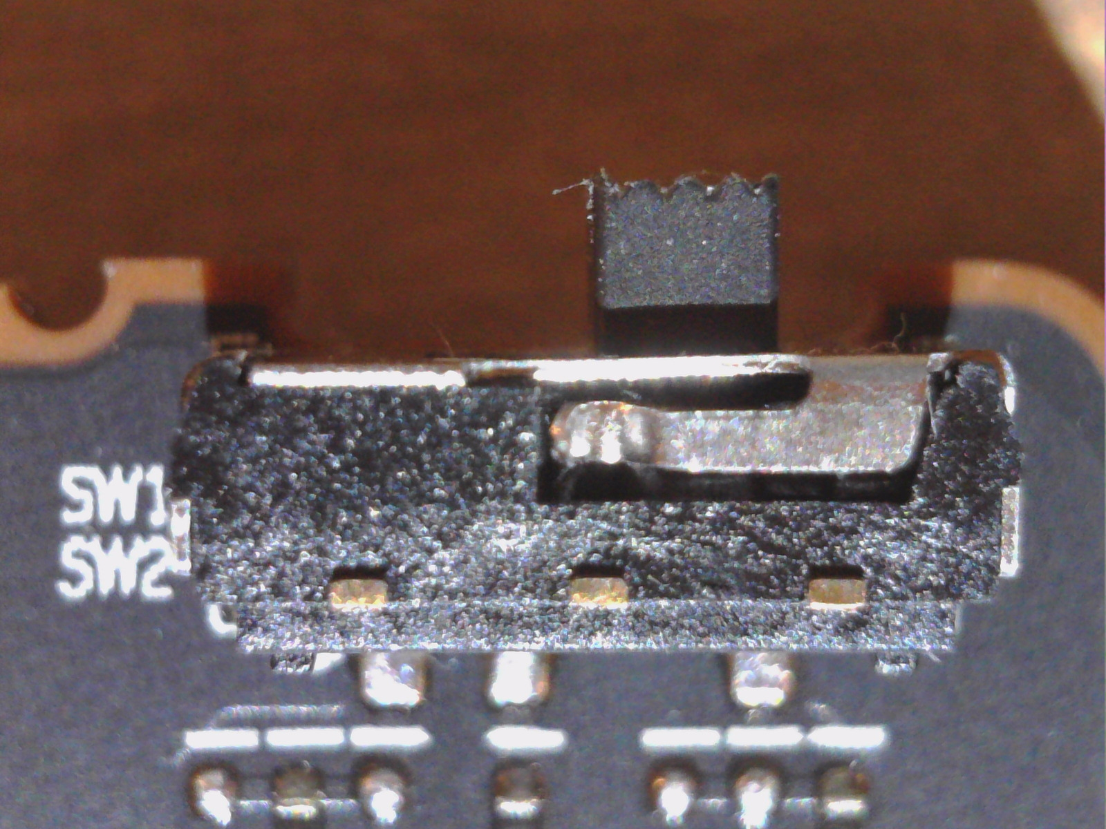
The coils of the now to 3 phases increased voltage supply of the memory have only 120 mH instead of 150 mH inductance compared to the reference. The BIOS switching is done by a simple DIP switch on the top of the PCB. One of the BIOS chips is positioned on the front side of the board, the other just below it on its back side.
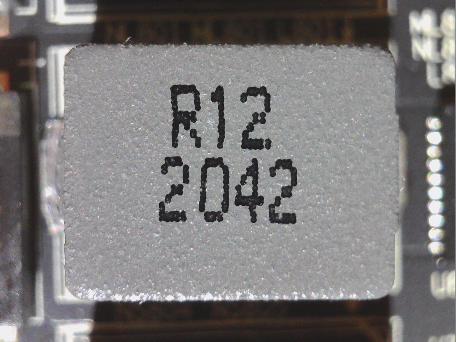
Once again, we see Samsung’s 2GB modules here, which are 16Gbps GDDR6 memory. To the right the LC filter for input decoupling of the power supply.
The back panel is quite tidy and you won’t find any SP or POS caps below the BGA. in general, everything looks very high-quality in large parts and otherwise at least very purposefully equipped. Instead of elaborate design stunts, this one relies on solid home cooking, which can really please.
Cooler and backplate
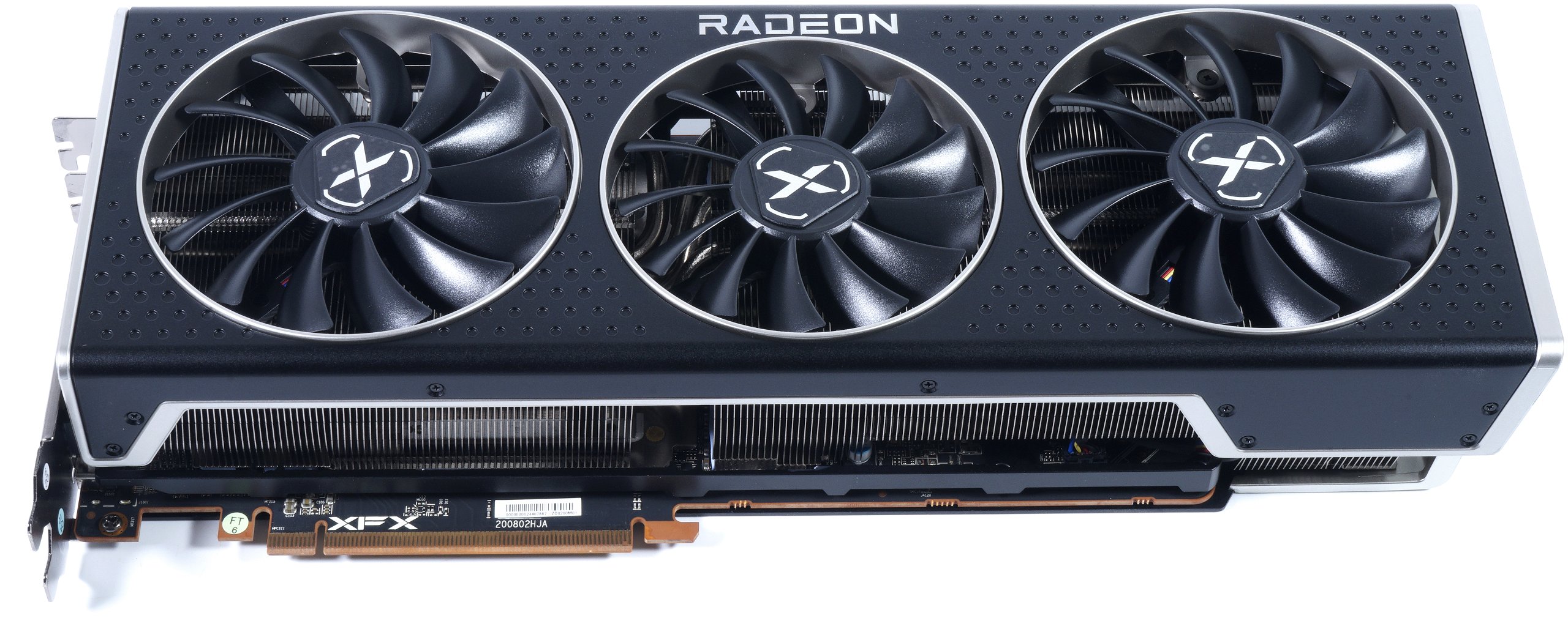
XFX uses two 9.5 cm fans with 13 rotor blades and one 8.7 cm fan with 13 rotor blades in the middle. The geometry of the impellers is very reminiscent of special fans for thicker radiators with a very high static pressure. This is not only the intention, but also the need for this high cooler, which significantly minimizes the breakaway noise due to the air refraction at the not too far apart cooling fins. In this way, the same noise emission is achieved despite higher speeds, but the throughput and pressure are significantly increased, which always helps the cooling performance.
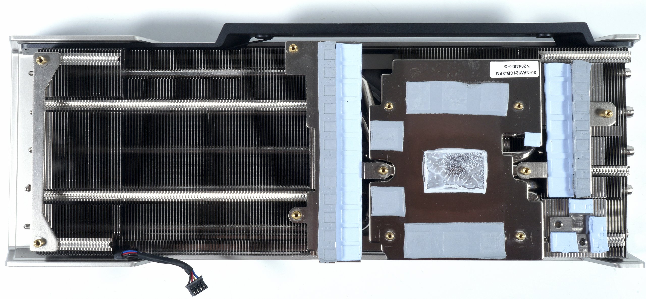
The cooler is divided into the rather massive and very long main cooler with various 6mm heatpipes made of nickel-plated copper composite material, which were flattened behind and soldered to the also nickel-plated GPU copper heatsink. The heatsink also cools the memory. Directly blown cooling fins are also set above this. This design is much heavier and more massive than Sapphire’s solution. The voltage converters are each cooled via a separate heatsink in the large cooler.
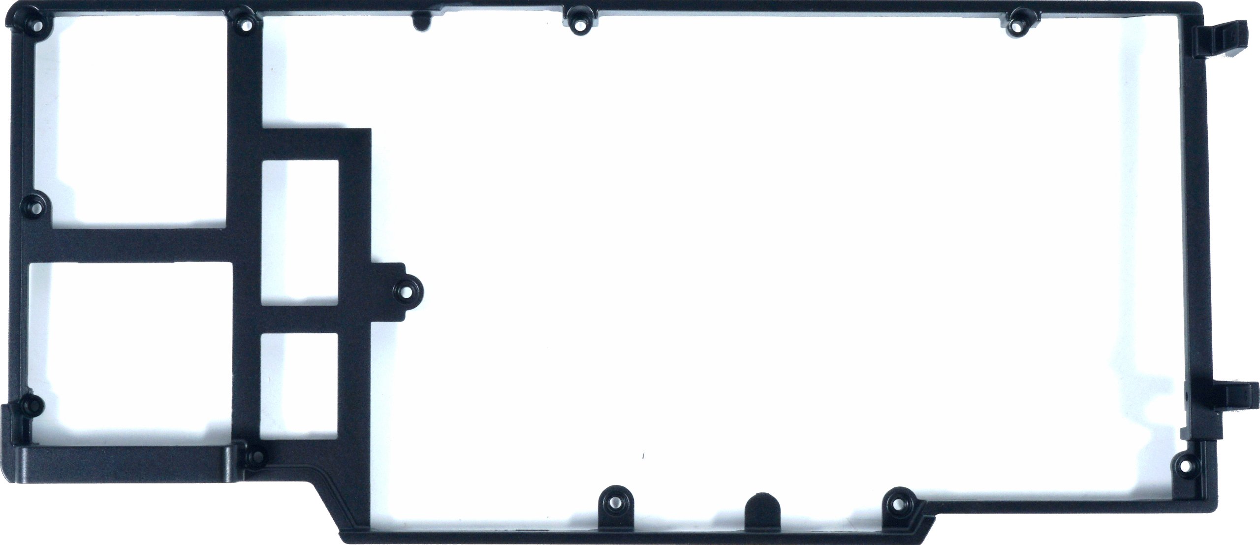
Since the cooler turns out to be very heavy, one relies on a circumferential stabilizing frame for the PCB on the front, which is screwed to the back of the backplate.
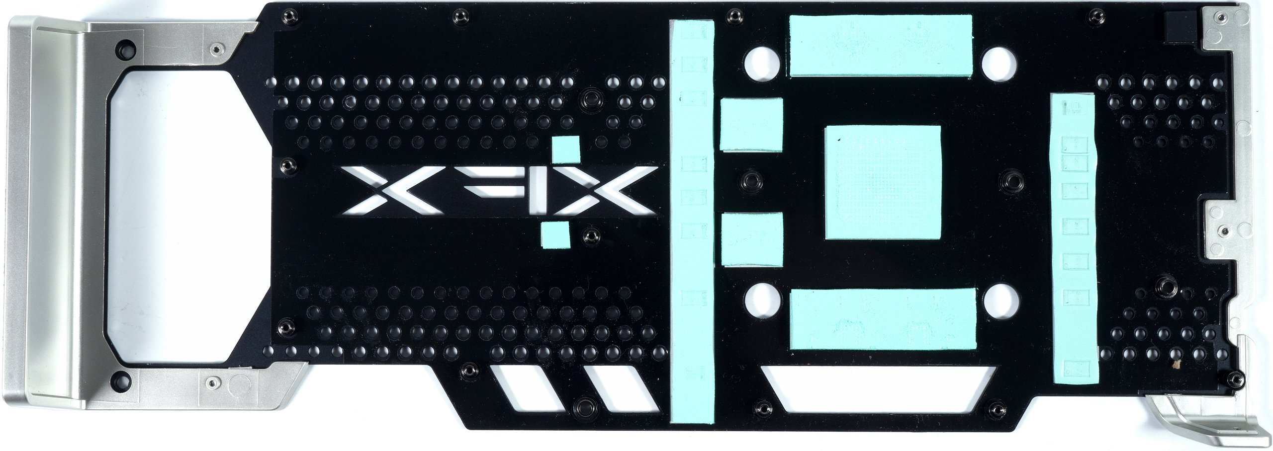
The backplate is another part of the stabilization and also an optical eye-catcher. The use of thermal pads is almost excessive, but would not have been necessary.
- 1 - Introduction and Technical Details
- 2 - Teardown: PCB and Cooler
- 3 - Gaming Performance
- 4 - Power Consumtion in Gaming and Efficiency
- 5 - Power Consumption in Detail, Voltages and Standards
- 6 - Transients and PSU Recommendation
- 7 - Clock Rate and Temperatures
- 8 - Fan Speed and Noise
- 9 - Summary and Conclusion


Kommentieren