


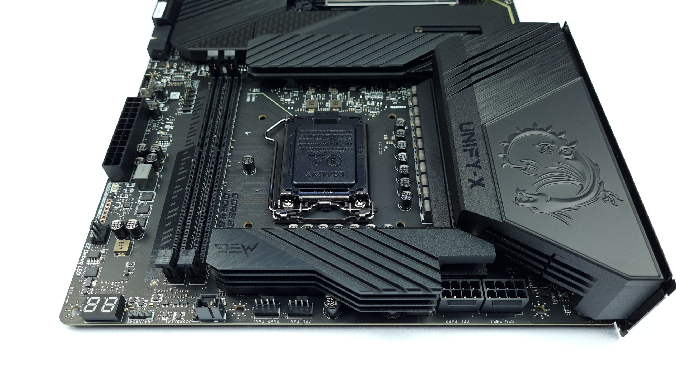
At the upper edge of the board there are 2 8-pin EPS connectors, two fan or pump headers, RGB connectors of various standards and the for overclocking almost indispensable postcode display. Along the right edge there are only voltage measuring points before a vertical 24-pin ATX connector follows. To the left of the USB 3.1 Type C port, there are a few jumpers for various OC functions, but there are no dedicated buttons.
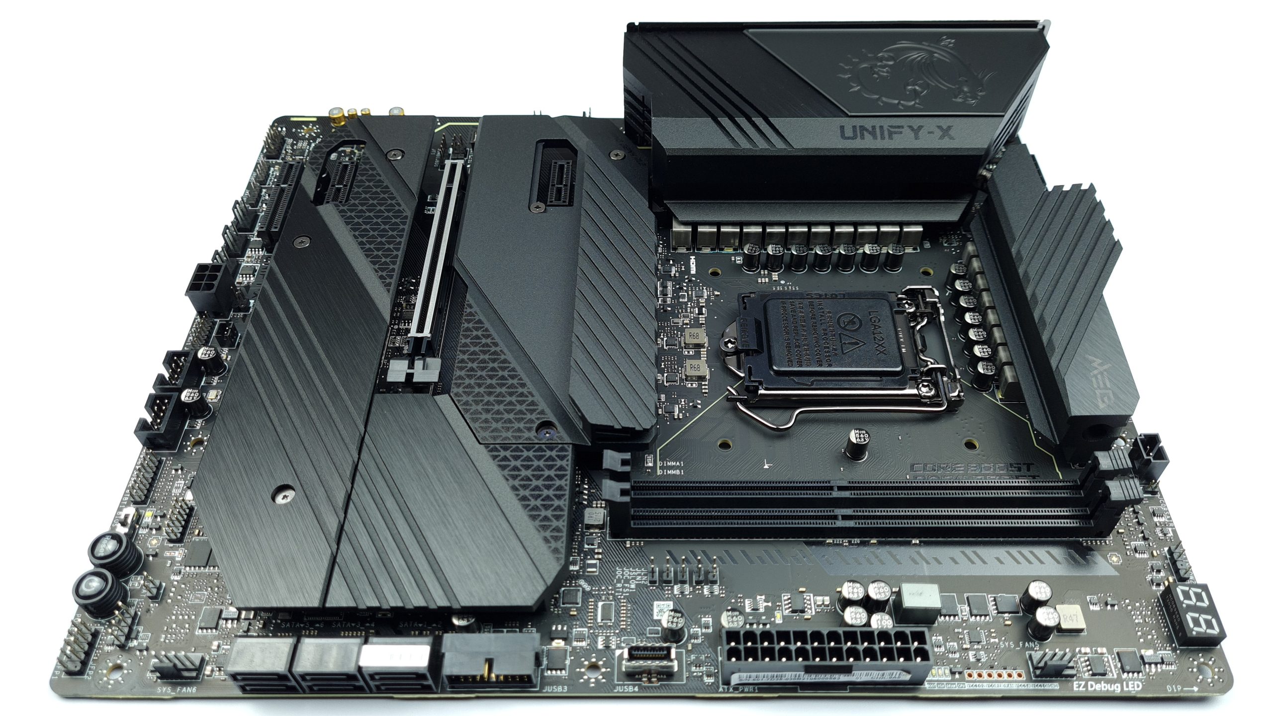
An internal USB 3.0 port follows in the bottom half, and next to it are the usual 6 SATA ports of the Z590 chipset. One fan connector later, we’re already at the bottom edge, where the only input elements on the whole board are located, two buttons for power and reset and a switch to select between the two BIOS chips with an indicator LED.
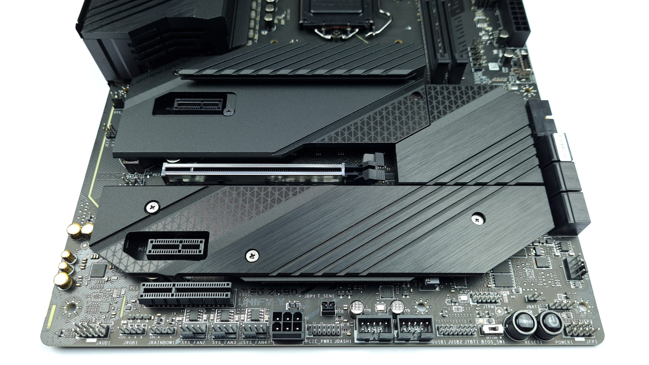
At the bottom edge there is a Thunderbolt connector, two USB 2.0 headers, the dashboard connector for the tuning controller, a PCIe 6-pin for additional power supply of the PCIe slots, 3 4-pin PWM, 2 RGB and the HD Audio header. But why do you need Thunderbolt on an XOC board and of what use is additional power supply for a single PCIe x16 slot, I would like to question.
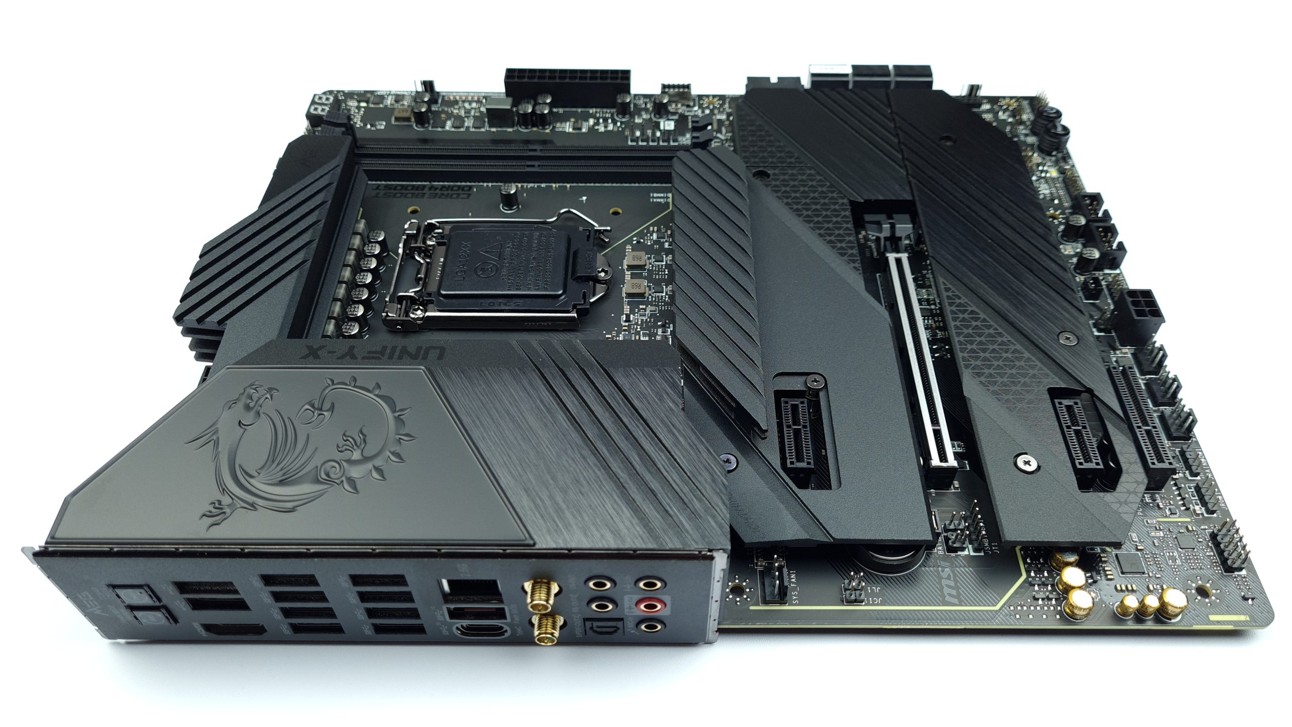
On the left edge, as usual, is the separate audio section of the board, with gold capacitors that unfortunately spoil the overall visual picture, as is so often the case. We can also see the CMOS battery here, unfortunately not easily accessible, but at least the screws for the M.2 cover can all be removed from the front.

MSI really didn’t skimp on the IO. Buttons for CMOS Clear and BIOS Flashback, twelve USB ports, 2 of them 2.0, 8 3.0 and 2 3.1, one of them Type C, HDMI output for the iGPU, Intel 2.5 Gbit Ethernet, WIFI 6E and 7.1 audio. Windows XP focused PS/2 ports like on other XOC boards are not included here.


4 Antworten
Kommentar
Lade neue Kommentare
Mitglied
1
Mitglied
Mitglied
Alle Kommentare lesen unter igor´sLAB Community →