


Teardown
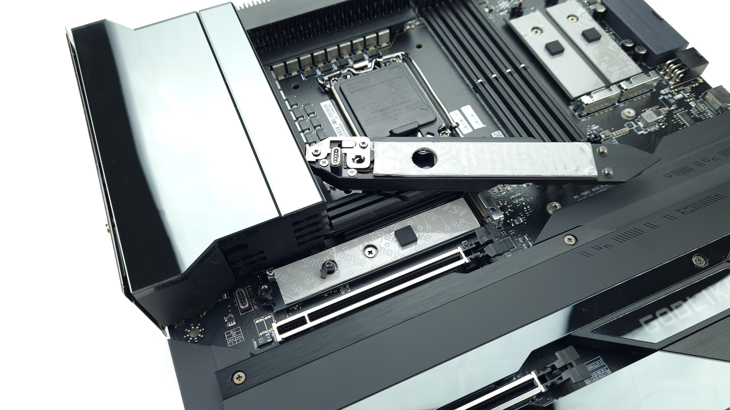
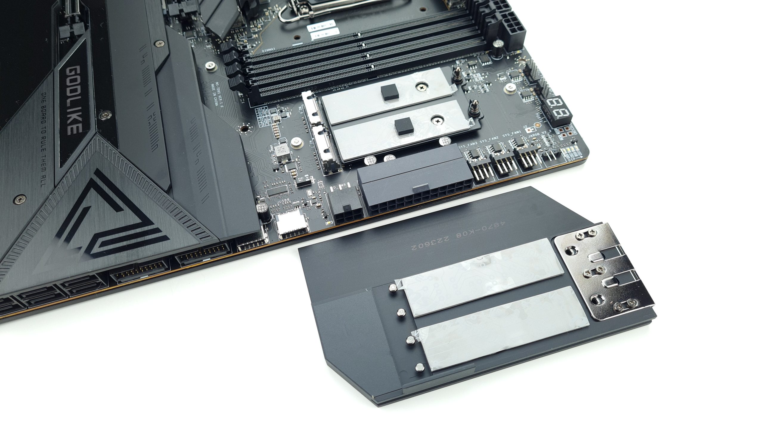
Let’s start the teardown by uncovering the numerous M.2 slots. Starting with the one at the top right, next to the RAM slots. This cover is toolless and can be easily removed by pressing down on it lightly. Thermal pads are already prepared on both sides here. The cover of the M.2 slot above the first PCIe slot is also toolless and has additional magnetic, pressure contacts for the RGB power supply.
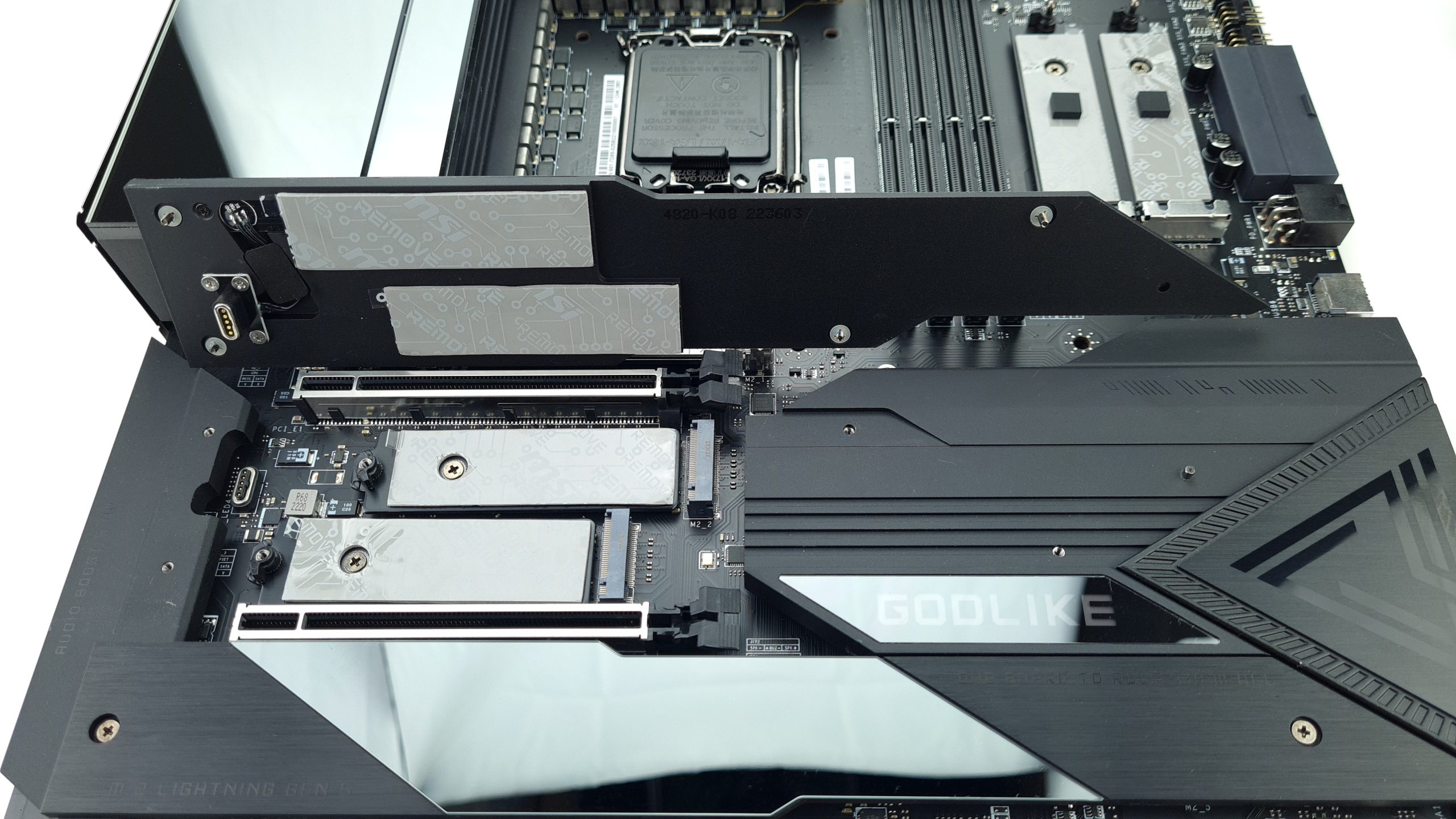
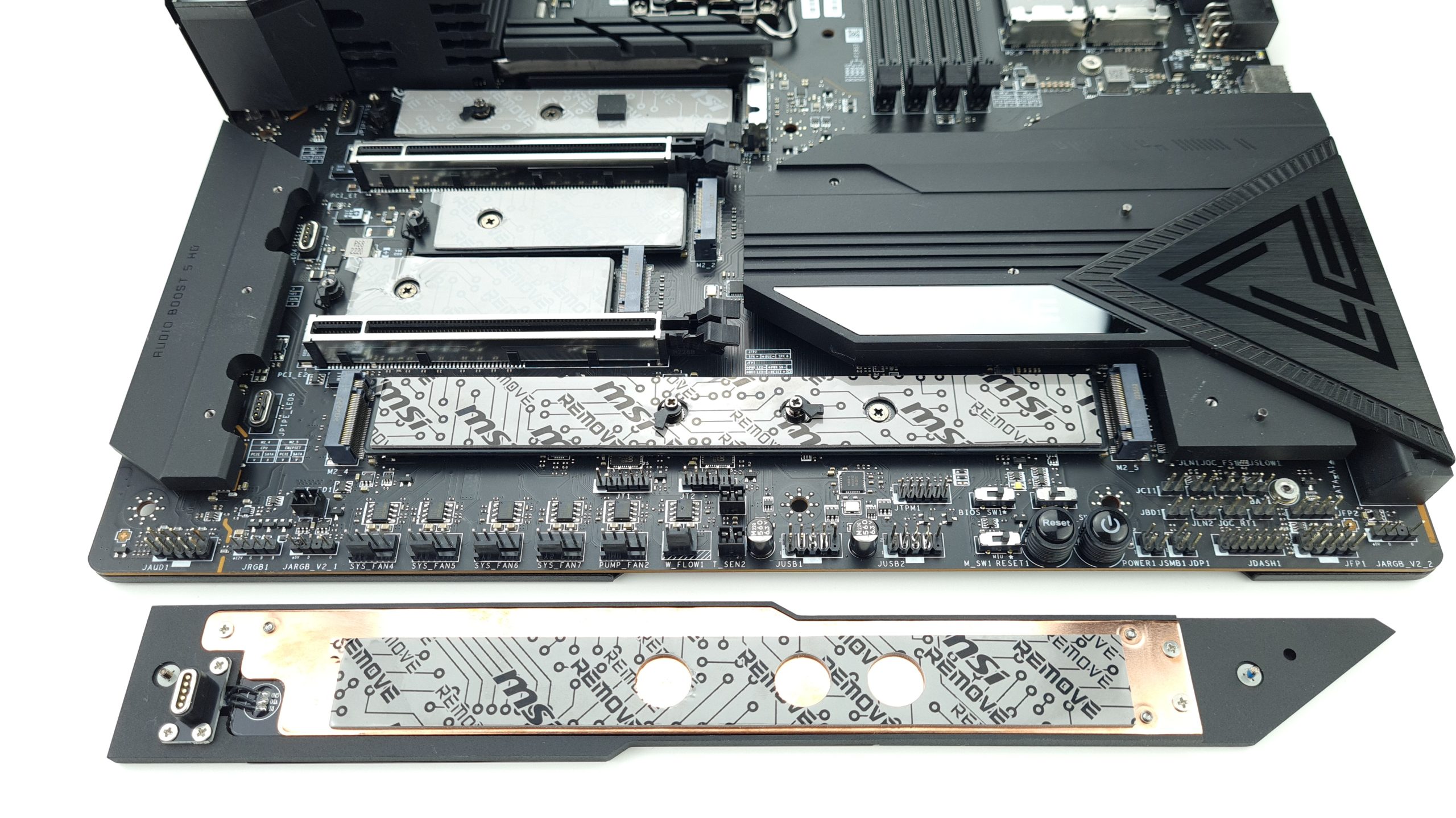
The other M.2 covers are attached with screws, but secured to the respective cooler, merging into the chipset heatsink. While the two middle M.2 slots are again provided with a normal aluminum heat sink, the lower two are additionally graced with an embedded copper strip. Thus, a correspondingly higher cooling capacity is already prepared for the only PCIe 5.0 M.2 slot on the bottom left. However, this would first have to be proven in practice, because although copper conducts and distributes the heat better, the surface of the heat sink is still unchanged towards the top.
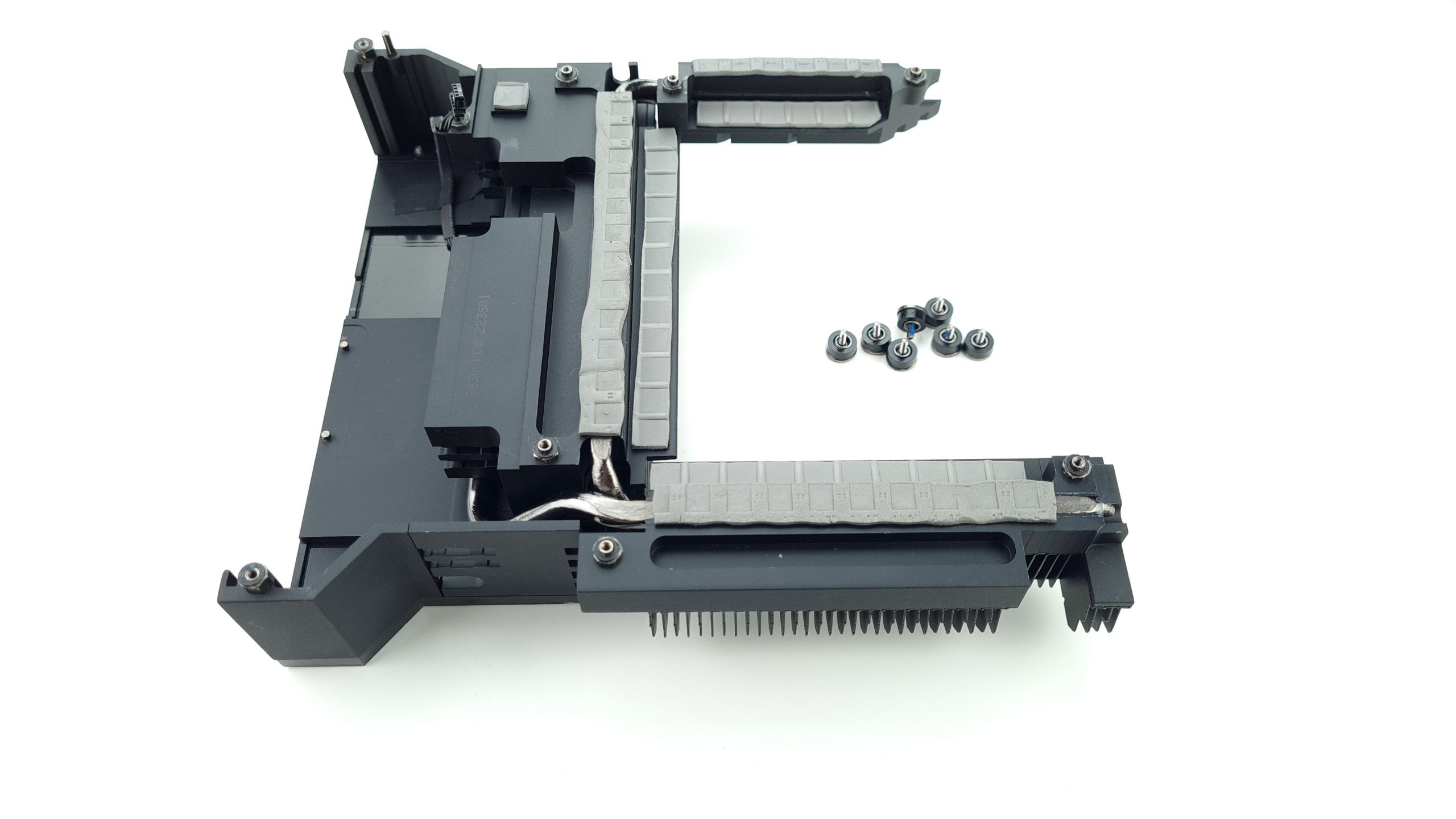
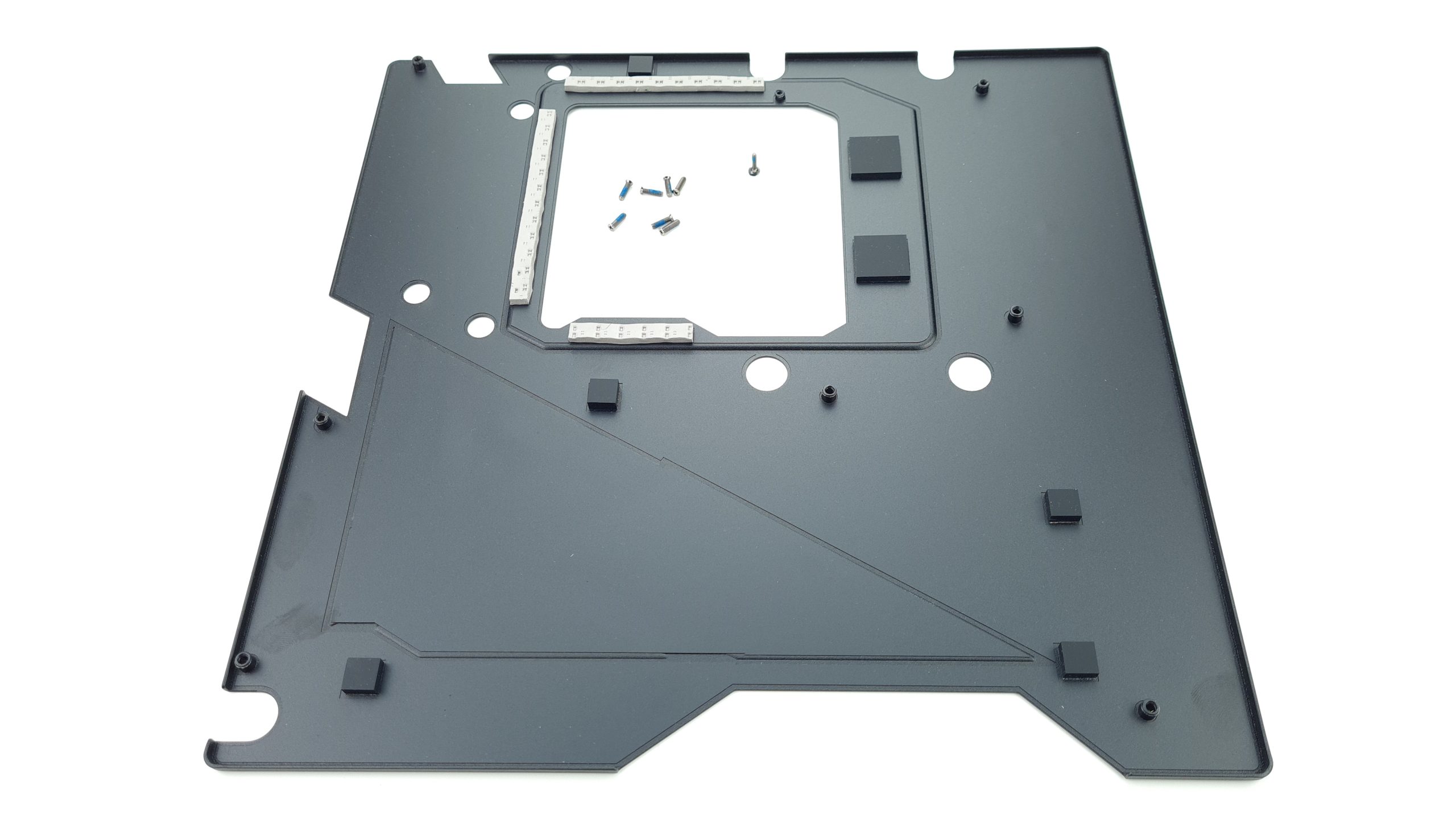
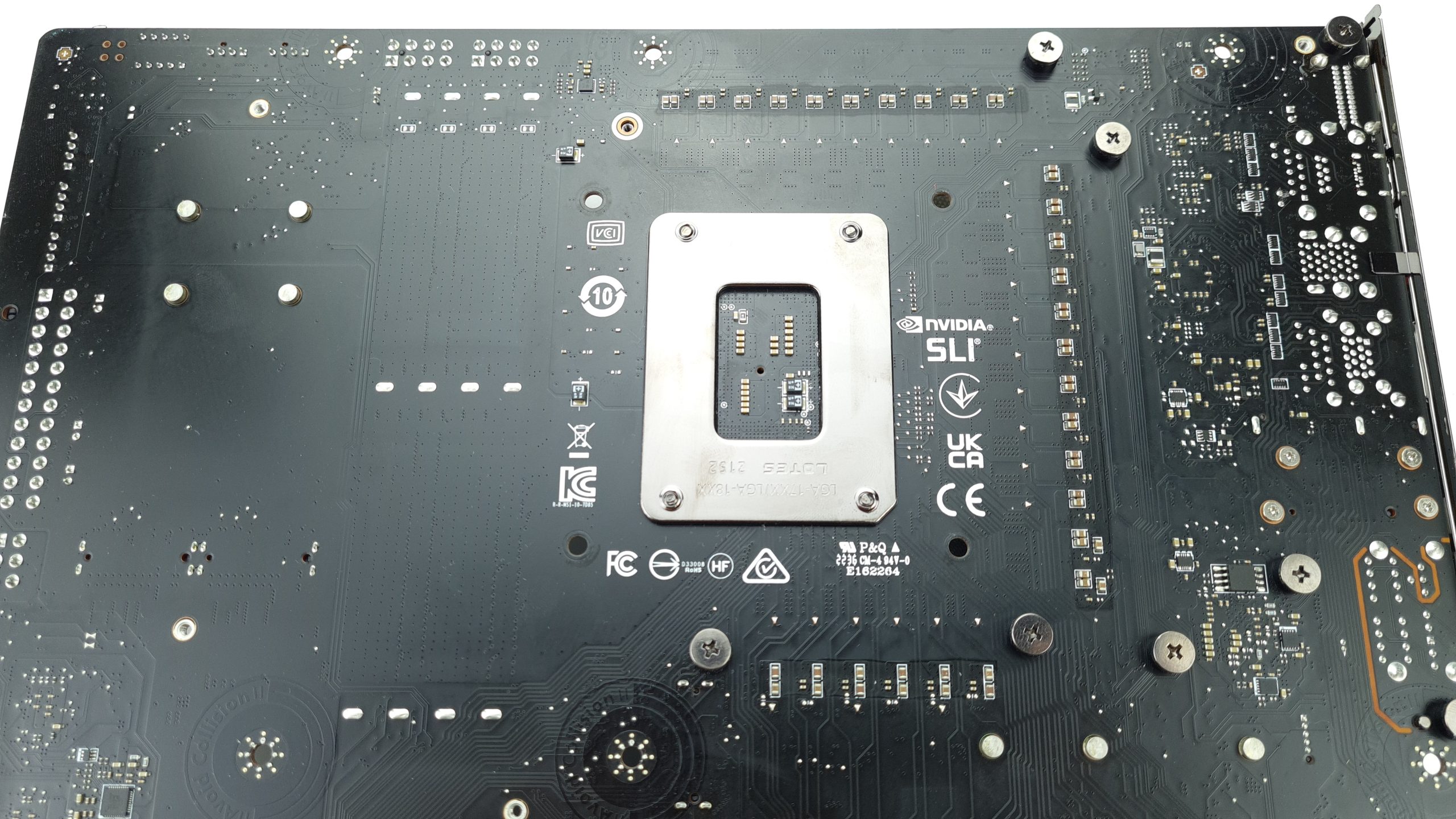
The backplate is screwed through the board from the front and can thus be removed without removing the chipset or VRM cooler beforehand. The board is also stabilized on the backplate with spacers and additionally with thermal pasds cools the voltage converters from the back. Their heat sink is again screwed from the back and consists of a single unit that merges into the IO cover. Two integrated heat pipes provide the appropriate distribution of the heat here. Thermal pads on the voltage converters and coils absorb it, and a specially milled section with fins ensures that the heat is released into the environment optimally.
PCB analysis
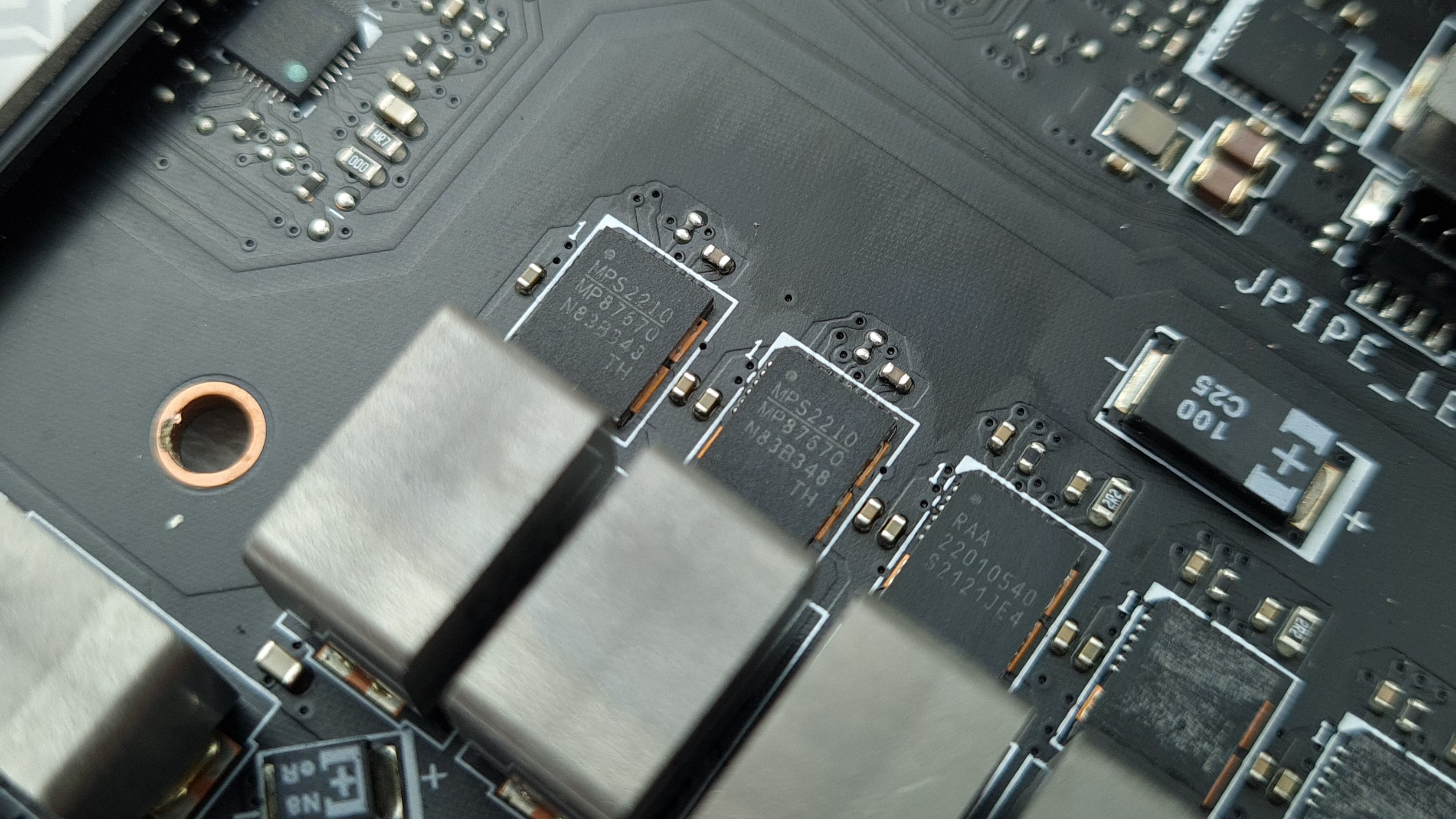
Now that the board is completely exposed, we can analyze the power supply for the CPU. This is arranged in a U-shape around the LGA1700 socket and uses 26 RAA 22010540 105 A Smart Power Stages from Renesas for the CPU core voltage (Vcore). Two Monolithic Power Systems MP87670 80 A DrMOS components supply the 1.8 V AUX voltage for the integrated voltage converter (FIVR) of the CPU. Unfortunately, there is no power supply for the integrated GPU (iGPU) on this board, and together with the missing display outputs on the IO-Shield, the question of iGPU support should also become superfluous.
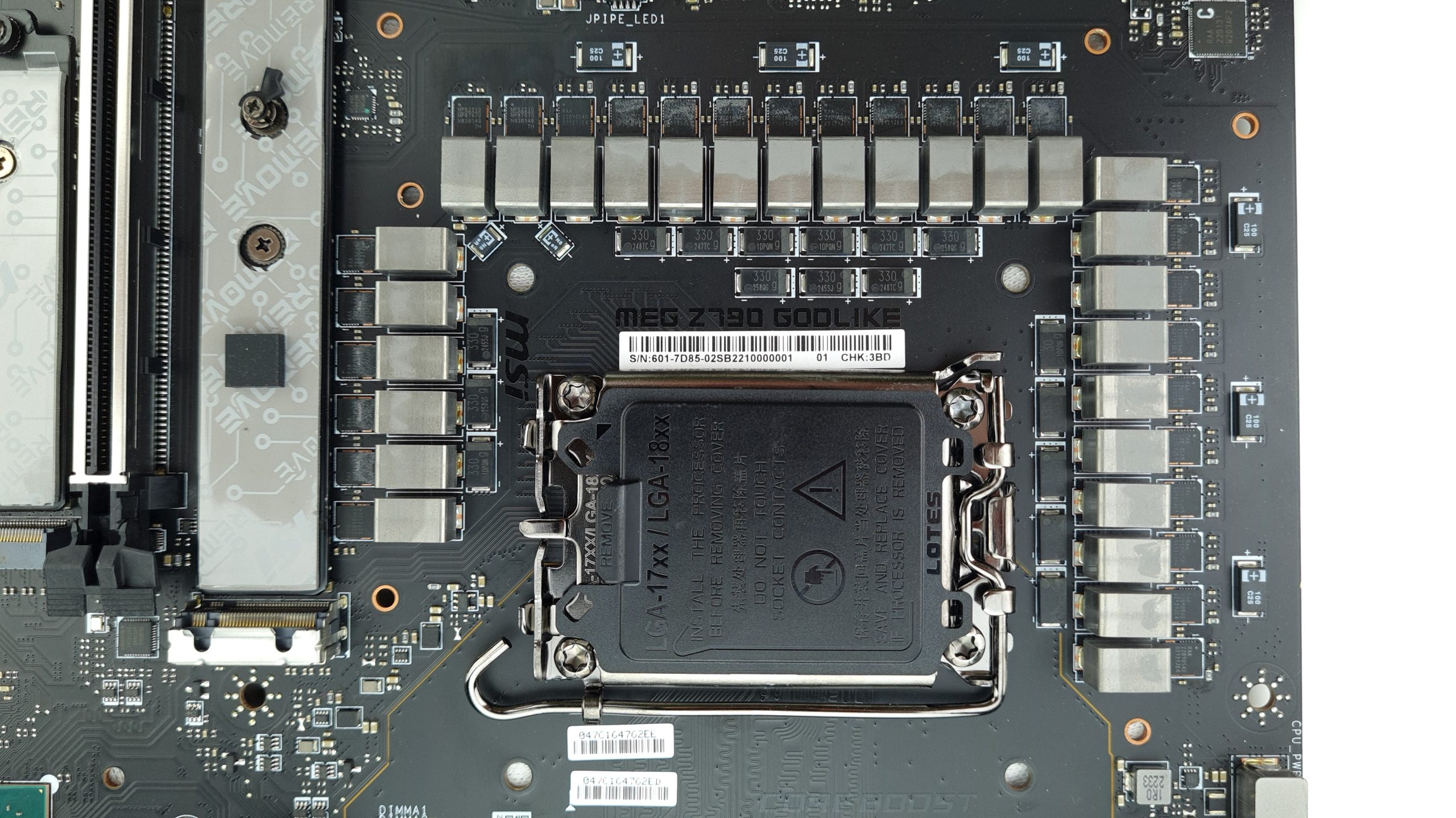
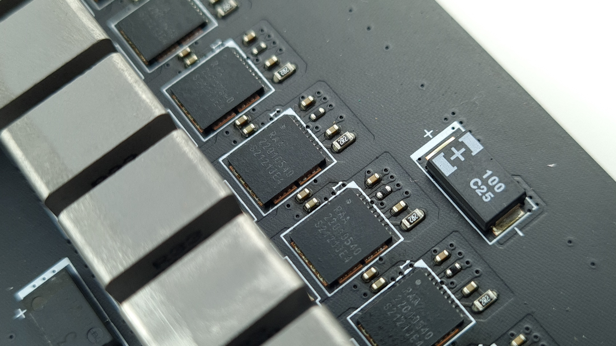
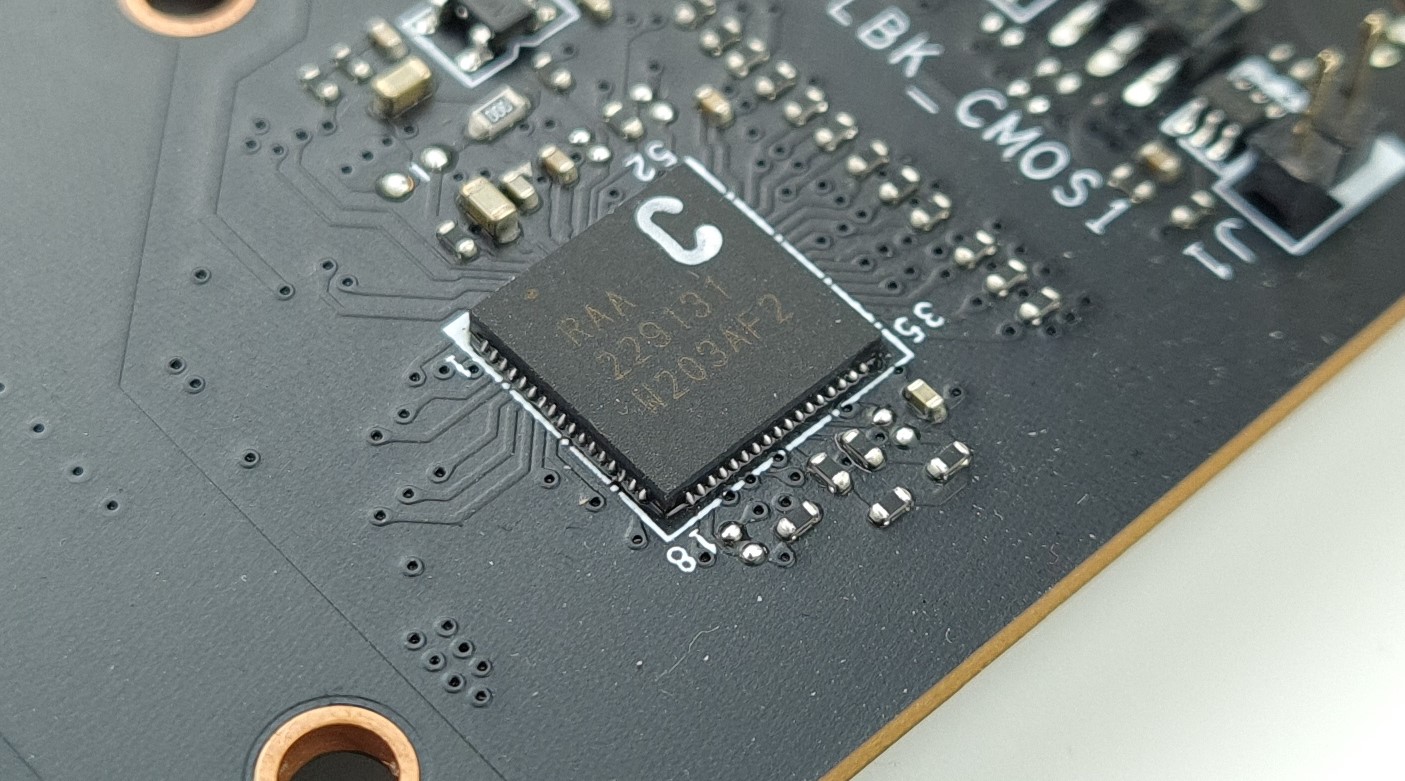
The power stages for Vcore are driven by a Renesas RAA 229131 20 (x+y <=20) phase PWM controller. Since there are no doublers on the board, two phases each would have to be run in parallel as a team for Vcore, effectively creating a 13*2 layout.
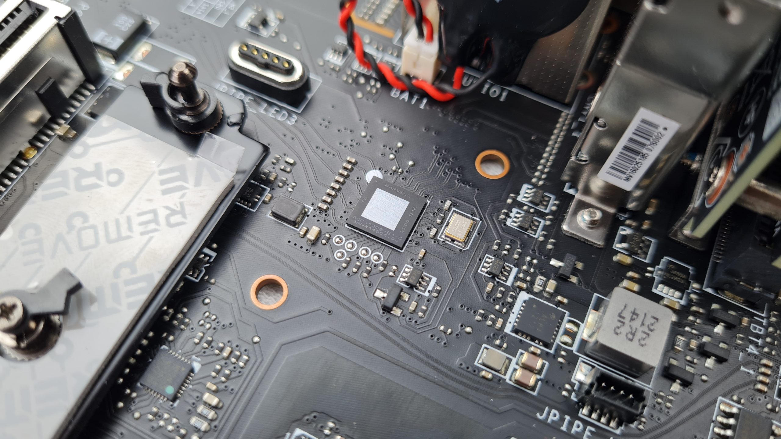
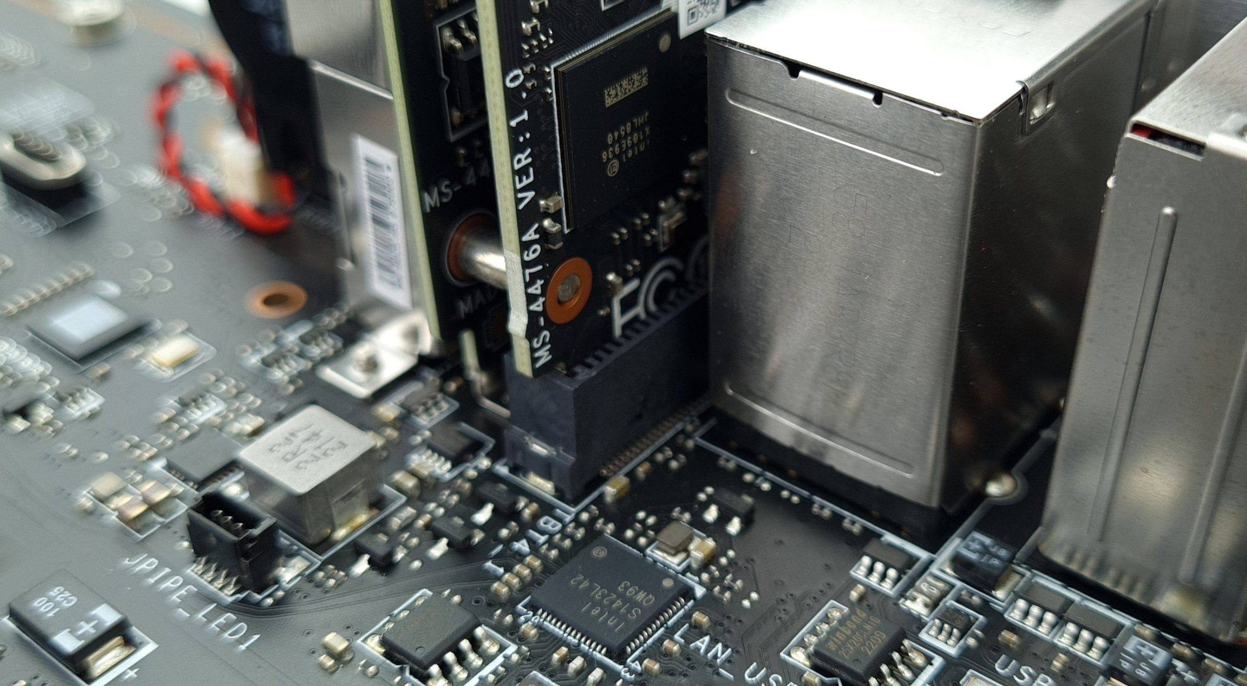
Other notable components on the board are the network controllers, for 10 GBE the Marvell AQC113, for 2.5 GBE the Intel I226 (QW93) and for Thunderbolt 4 on the fixed riser card the Intel X109 chip.
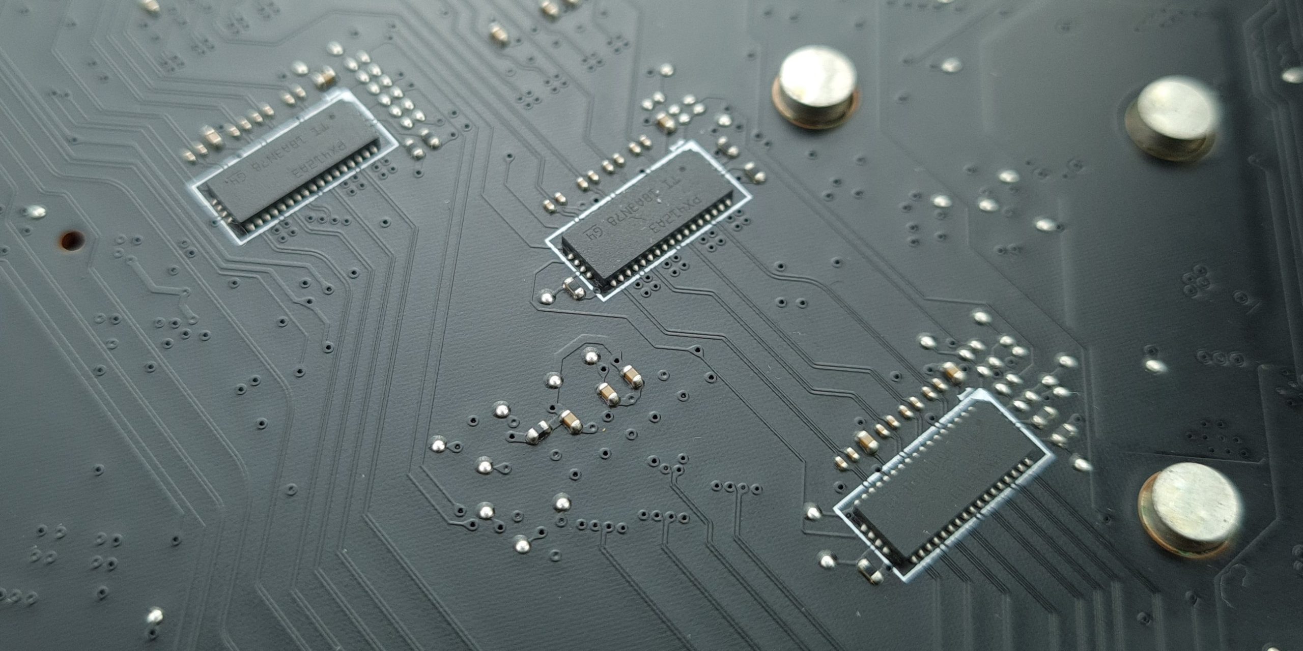
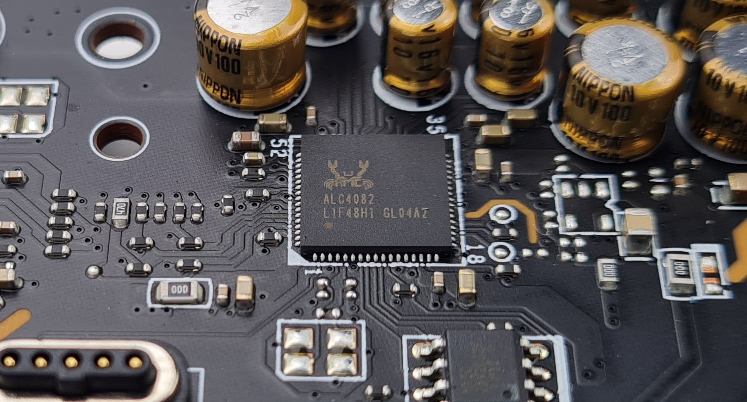
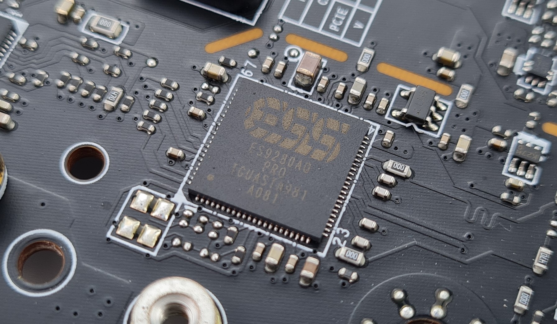
Texas Instruments PX412A3 PCIe 5.0 Redrivers provide the connection of the lower PCIe slot with up to x8 and thus enable the SLI certification of the motherboard. An ALC4082 codec from Realtek and an ES9280AQ Quad DAC from Esstech take care of the on-board audio. For the pcb MSI uses an 8 layer design.


17 Antworten
Kommentar
Lade neue Kommentare
Veteran
Veteran
Urgestein
Urgestein
Mitglied
Veteran
Veteran
Mitglied
Veteran
Urgestein
Mitglied
Urgestein
Urgestein
Mitglied
Veteran
Mitglied
Alle Kommentare lesen unter igor´sLAB Community →