


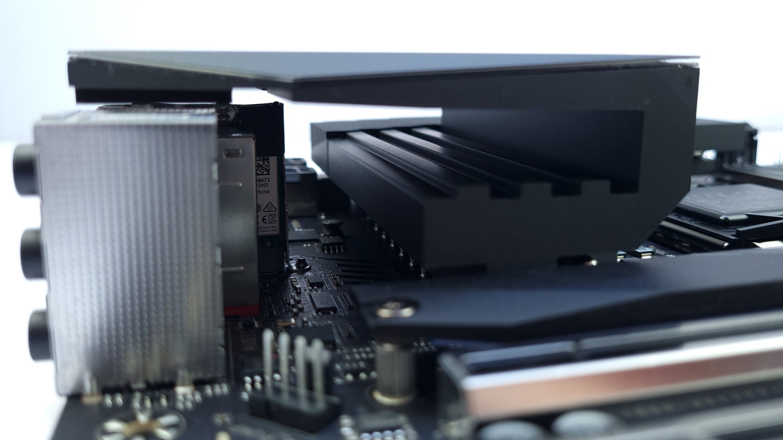
The two heatsinks for the M.2 slots, the chipset cooler and the VRM cooler are each a component made of aluminum and can be easily removed with a few screws on the back. Thermal pads are already pre-installed on the former, so you only have to remove the protective foil before use. The chipset cooler is still connected to the board with a single black ribbon cable for the RGB lighting, but its connector can also be easily removed.
Gigabyte has spared no effort and raw materials when it comes to the cooler for the power delivery, in order to design it aesthetically appealing, functional and completely passive at the same time. Below the Tachyon logo, the cooler is effectively recessed, creating a kind of convection tunnel from the bottom to the top, with additional notches on the underside providing sufficient cooling performance in an elegant way.
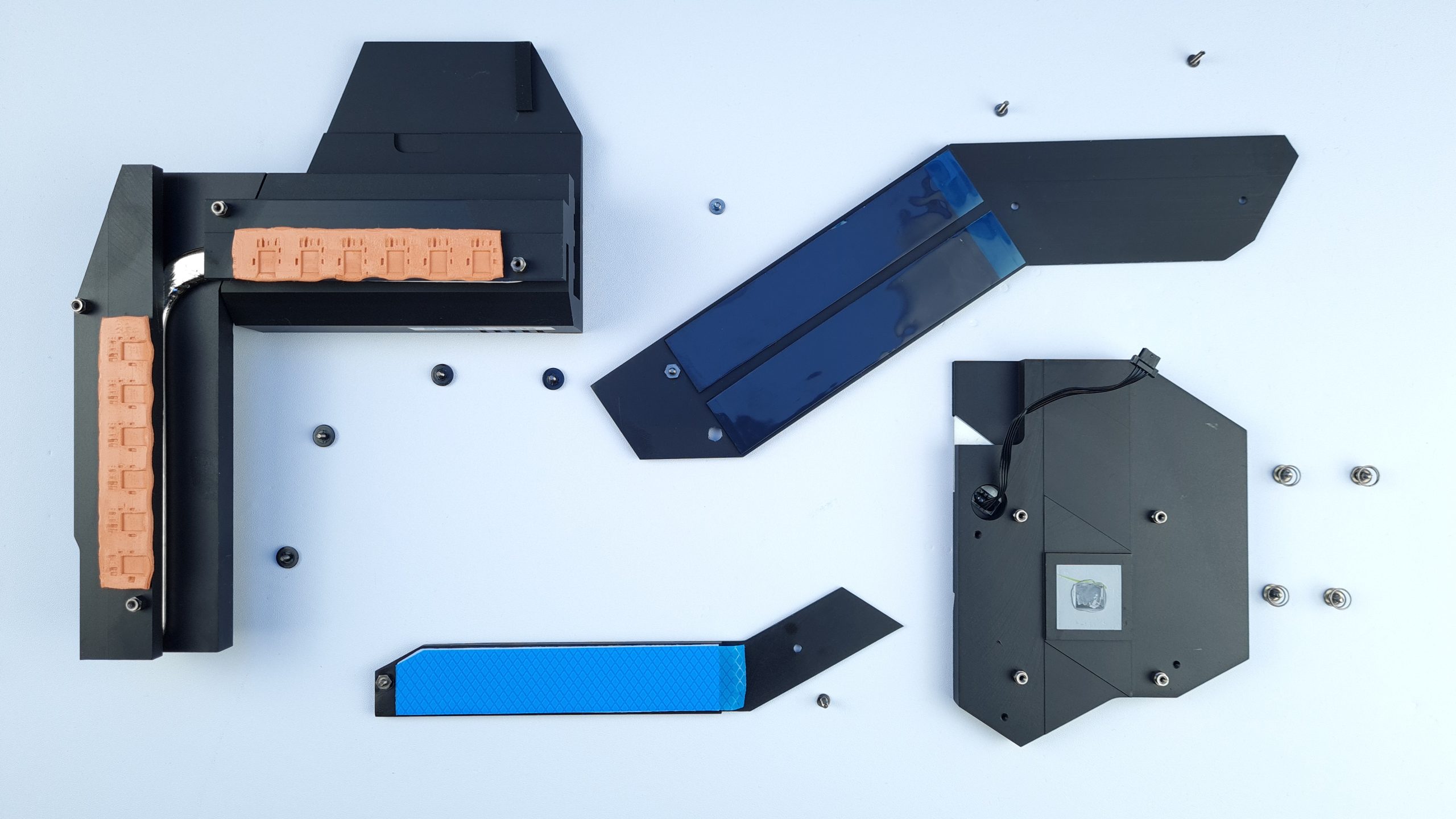
In addition, a flattened heat pipe runs through the entire heat sink, ensuring the most even heat distribution possible between the two aluminum components, which are attached to the voltage converters with orange thermal pads.
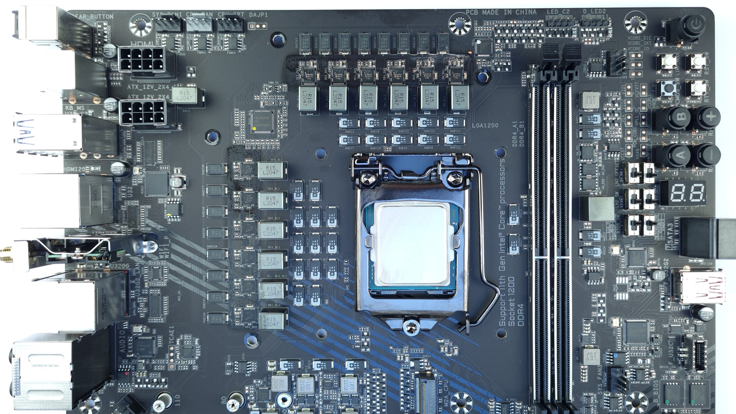

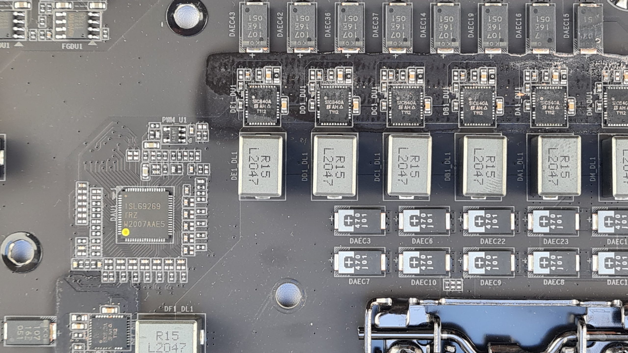
These are 12 SIC840A 100 A Smart Power Stages from Vishay, 11 of which are controled by an ISL69269 from Renesas for the Vcore voltage. In contrast to other boards with the same controller, no doublers are used here, but the power stages are directly controlled, which should theoretically provide lower response times for transient loads. The last phase of the PWM controller is used for the SA voltage with a Vishay SIC654A, specified as 50 A.
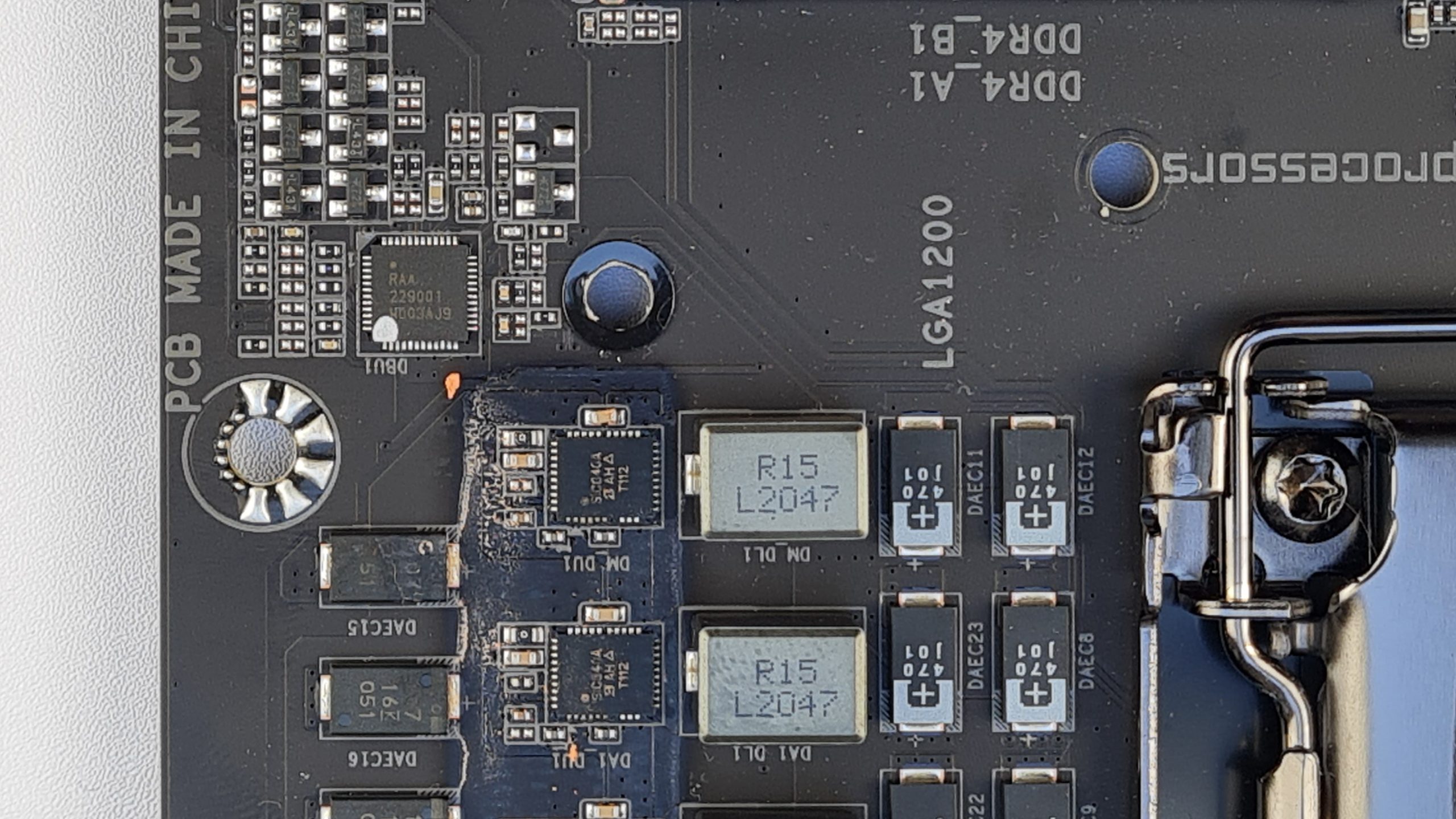
The last SPS around the socket is a single one for Vgt, which is the power supply for the integrated graphics unit, and is controlled by a dedicated RAA220001. So this is how Gigabyte gets their “12 + 1” phases, where in reality it’s 11 Vcore + 1 Vsa + 1 Vgt, but at least the rest of the small voltages aren’t lumped together as well. Speaking of which, two dedicated small NTTFS4C10N mosfets from OnSemi are used here for each of the IO and IO2 phases, as we already know from other Z590 boards.
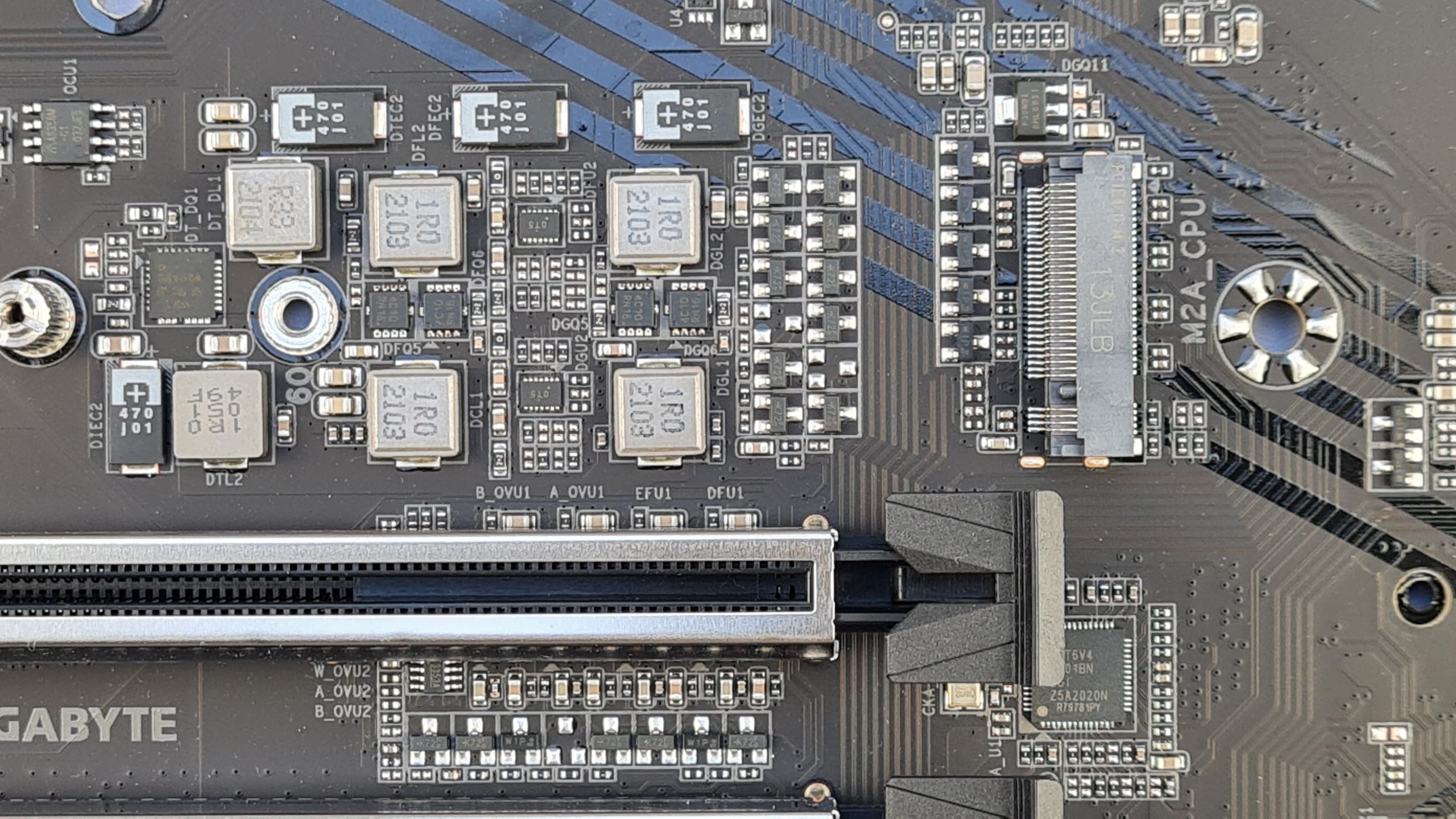
The controllers for these are located under the first PCIe slot, so they cannot be easily identified. Finally, the only thing missing is the Vdimm voltage for the RAM, for which three NTMFS4C06N mosfets from OnSemi are used in a 1-phase configuration. For voltage smoothing of the input and output sides of all VRMs, high-quality POSCAPs from Panasonic are used almost throughout, especially around the socket and even on its back side.

Although the marketing counts a little more generously with the power supply as is often the case, the overall design is really strong. The dimensioning is more than sufficient in any case and with 11 real phases for Vcore, the transient response is still a bit better than comparable boards, at least on paper. The fact that the selected power stages are not really intended for operation with 100 A and more efficient components exist should be mentioned, but with the massive passive heatsink Gigabyte already creates a very good solution for this.
If you want to know more details about the power supply and its efficiency, I recommend the video about the board by the Youtuber buildzoid.


15 Antworten
Kommentar
Lade neue Kommentare
Urgestein
1
Mitglied
Veteran
Urgestein
Urgestein
Veteran
Veteran
Neuling
Urgestein
Neuling
Urgestein
Alle Kommentare lesen unter igor´sLAB Community →