


Teardown: Satellite
Let’s first unscrew the active satellite on the right and take a look inside. By the way, Edifier has not been stingy with screws. The rather neatly glued together MDF body with its 10 mm sidewall thickness is sturdy enough, as it is neither a big box, nor does it have to withstand very much pressure.
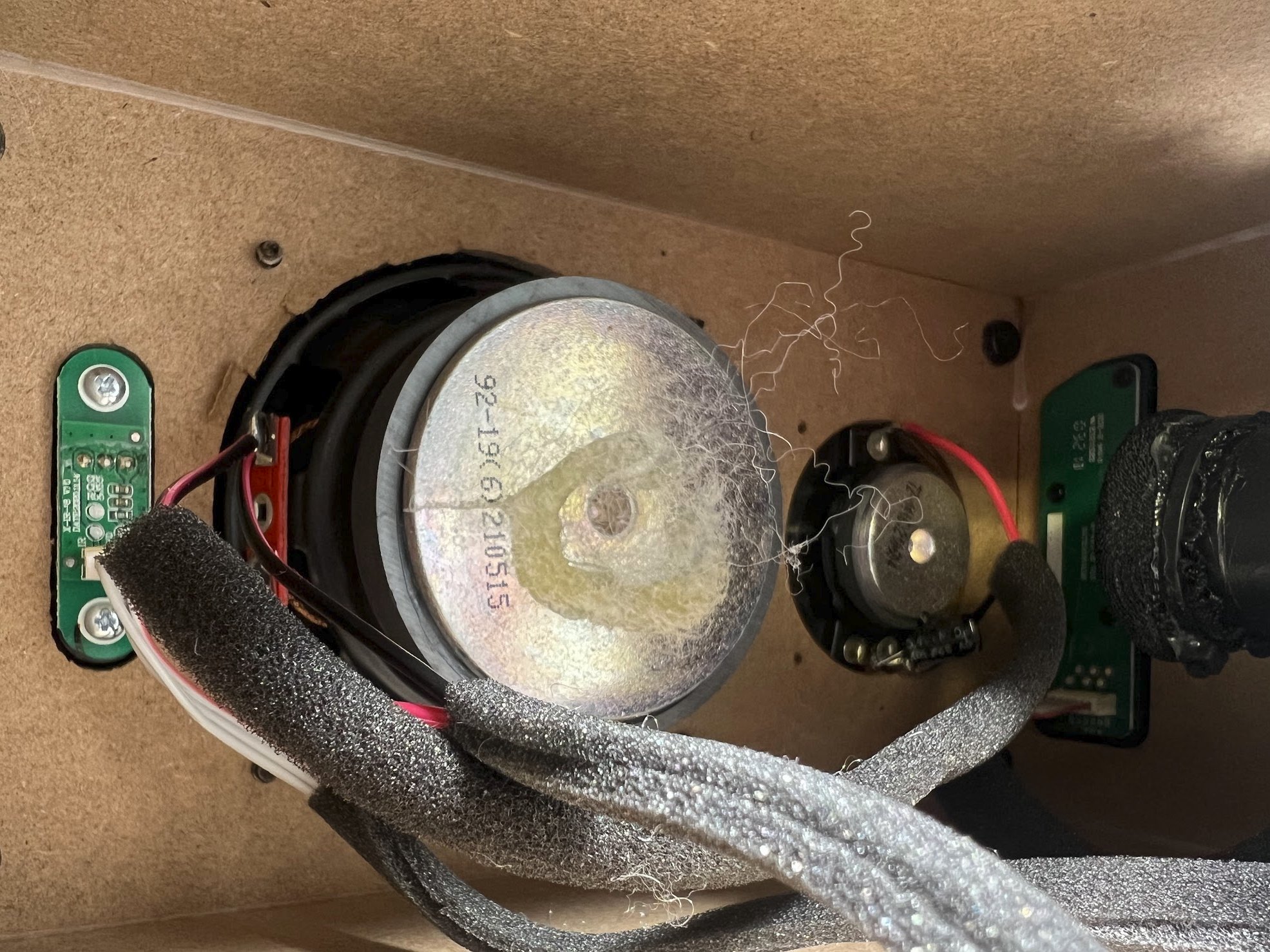
There is a relatively large amount of space inside, which is also due to the small speakers. While the opening of the tweeter has been cleanly cut out, the chipboard is already coming off all around the midrange driver. However, I’m sure that I caught an exception here, because the left speaker was fine. Still, something like this has to be noticeable on the QC and shouldn’t have been equipped with technology in the first place.
We also see that Edifier does without a real crossover, but only works with a simple longitudinal capacitor that keeps the low frequencies away from the tweeter. Since there is no coil to block the high frequencies at the midrange, quite a bit of high-frequency power is likely to be lost here. Unattractive, because there is no real transition. By the way, above the tweeter we see the end of the bass reflex tube and there behind it the circuit board of the three buttons on the top. The receiver of the IR remote control is placed in front on the left.
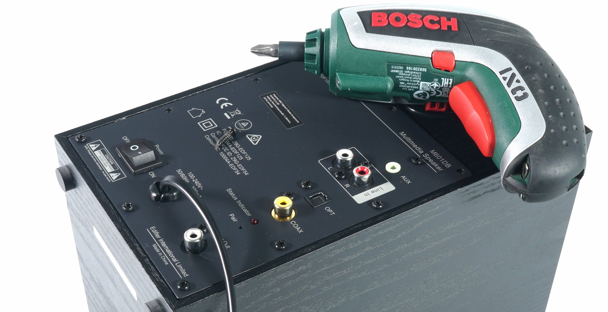
The panel carries a sufficiently sized switching power supply and a single-board solution for all assemblies. Edifier relies on an STM32F103 microcontroller with a Cortex-M3 core and a maximum CPU speed of 72 MHz, flash memory, USB full-speed interface and CAN for the controller. The PCB also carries two radio modules. On the left is the 2.4 GHz Bluetooth module with the antenna on the PCB and half-right the 5.8 GHz module for the subwoofer, also with integrated antenna.
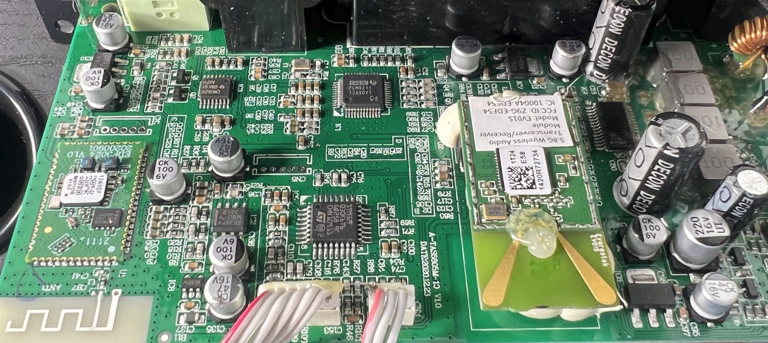
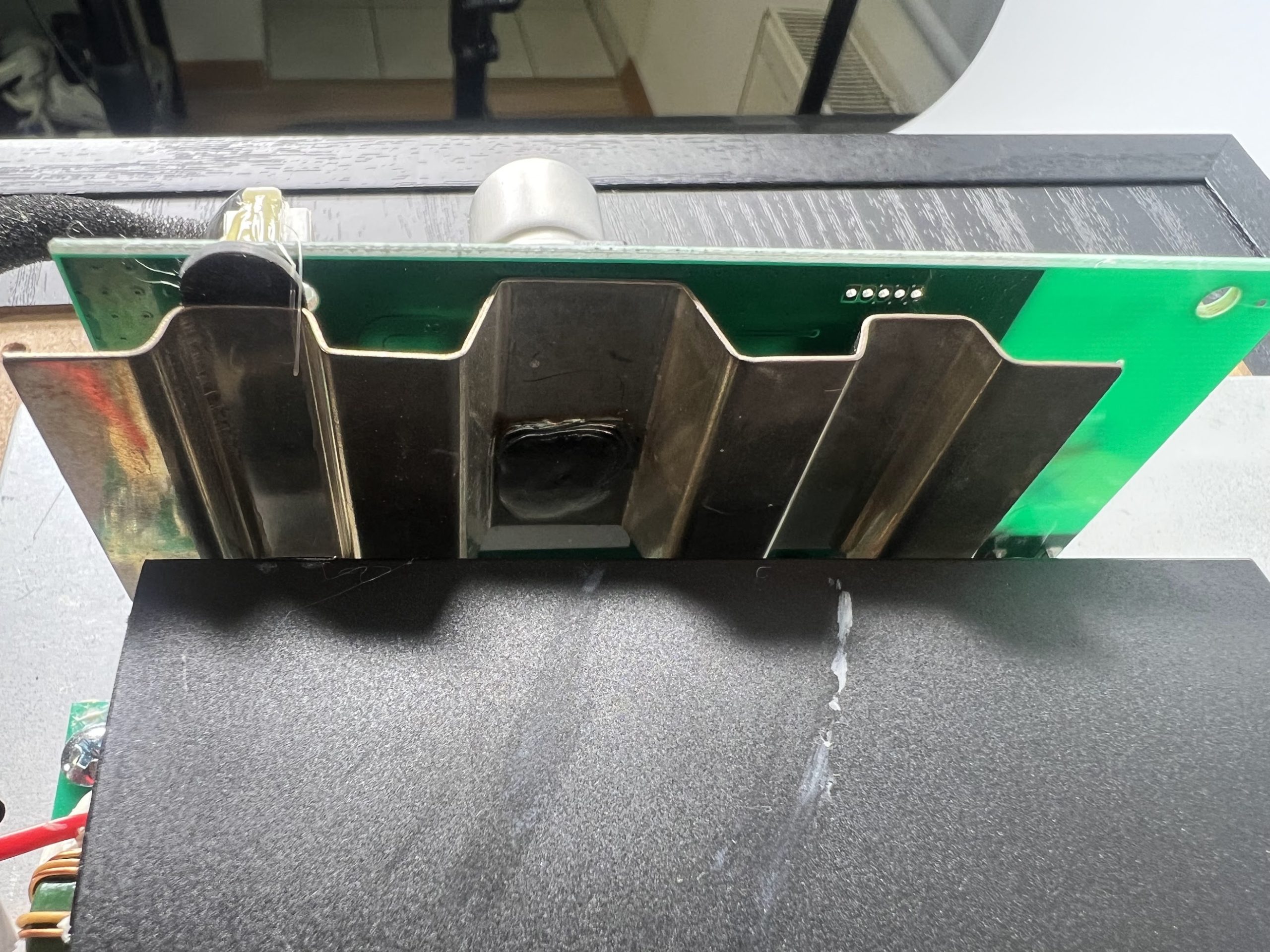
The built-in PCM9211 is a complete analog and digital front end for modern multimedia players, soundbars and recorders. It integrates a stereo ADC, an S/PDIF transceiver with up to 12 multiplexed inputs and three PCM inputs so that other audio receivers can be multiplexed, and the analog and S/PDIF signals to a digital signal processor (DSP). The chip for the power amplifier is stupidly completely covered in glue, which is absolutely nonsensical. Even though it might be an oversight, thermally something like this is actually the super-GAU. I carefully scraped it off bit by bit.
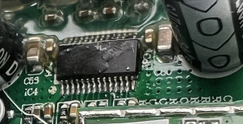
This is a 2-channel amplifier from Texas Instruments in a DKD package in the form of the popular TAS5805. This is a fairly efficient, digital Class-D stereo power amplifier with 23 watts RMS max per channel and many additional features. It offers an independent channel volume control with a 24-dB to -100-dB range, smooth mute (50% duty cycle), programmable dynamic range control, 16 adjustable biquads for speaker EQ, seven biquads for the left and right channels, and two biquads for the subwoofer channel.

But if the chip can do all that, why didn’t they implement any sound profiles or tone controls? Nothing can be controlled on the M601DB except the volume. The pure sine wave power of the M601DB’s satellites would be an honest 15 watts per channel, which is just about adequate, but not really much.
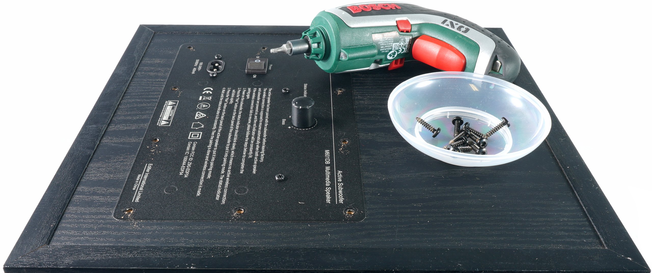
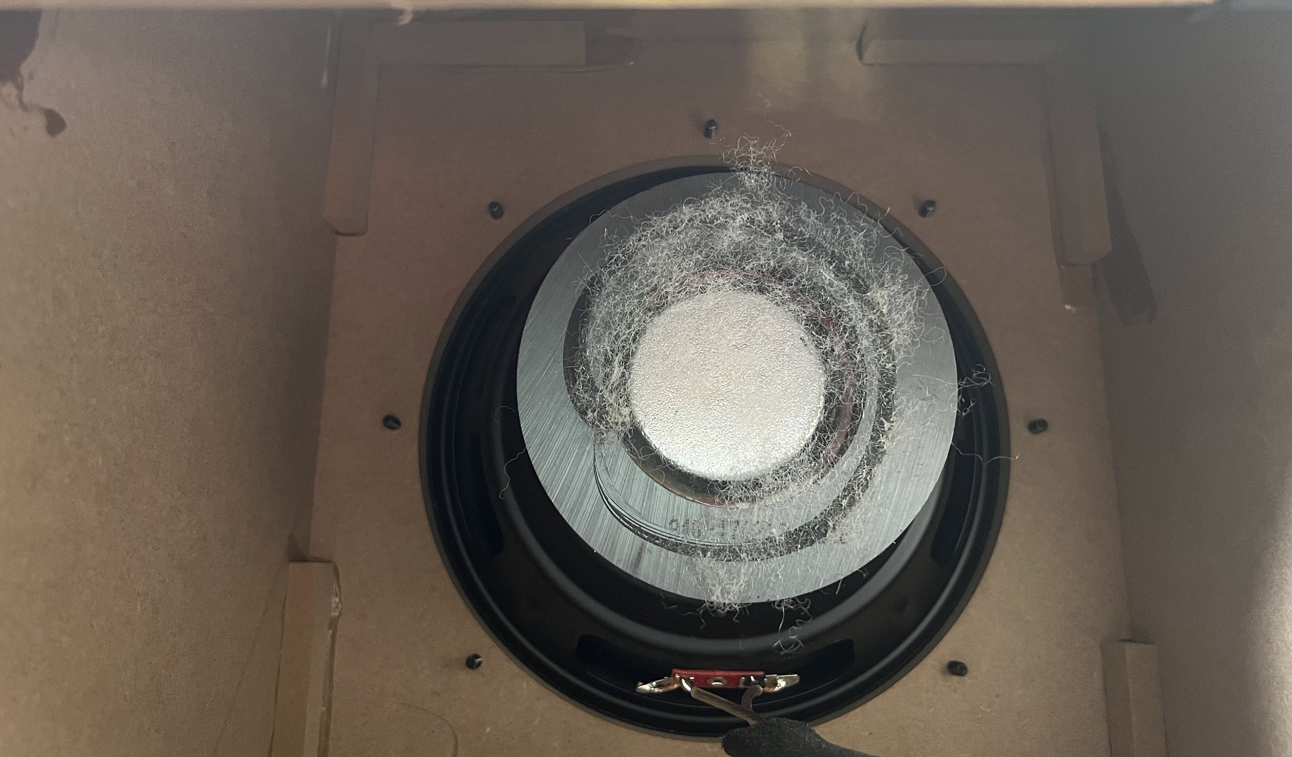
However, the subwoofer is also interesting and so, as always, I made my way inside. This time it was Torx screws, but of course something like that doesn’t stop me. Behind some alibi foam sits the woofer. It doesn’t have an extreme amount of excursion, but it’s quite enough for some pressure in small to medium sized rooms (about 25 m²). You can also see the stabilization of the edges by glued-on blocks.
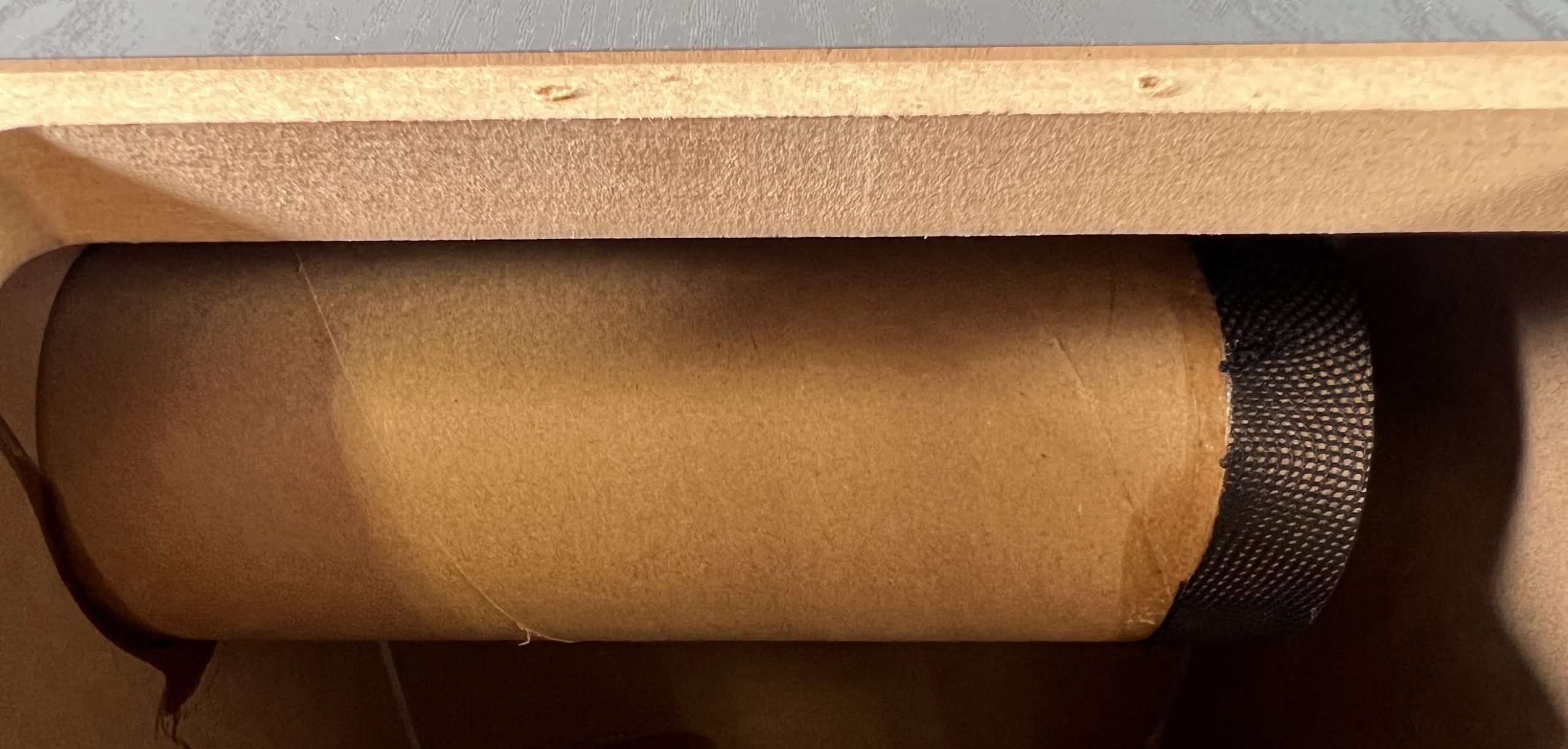
The whole thing is supported by a laterally positioned bass reflex tube. Here, Edifier has almost completely utilized the maximum possible length. You can see from the cross-section of the rear panel that the very fine-pored MDF boards are sufficiently thick and stable.
The circuit board doesn’t hide any secrets. We can see the glued-on 5.8 GHz radio module in an exposed position as well as the amplifier circuit in the center. Edifier relies on the TAS5754 from Texas Instruments here. The Class D amplifier is operated as a mono power amplifier in bridge circuit, whereby I would like to somewhat doubt the reported 70 watts RMS. Apart from the fact that the chip is only specified for 61 watts mono, I measure distortion-free 50 watts sine wave at 1 KHz with a lot of good will.
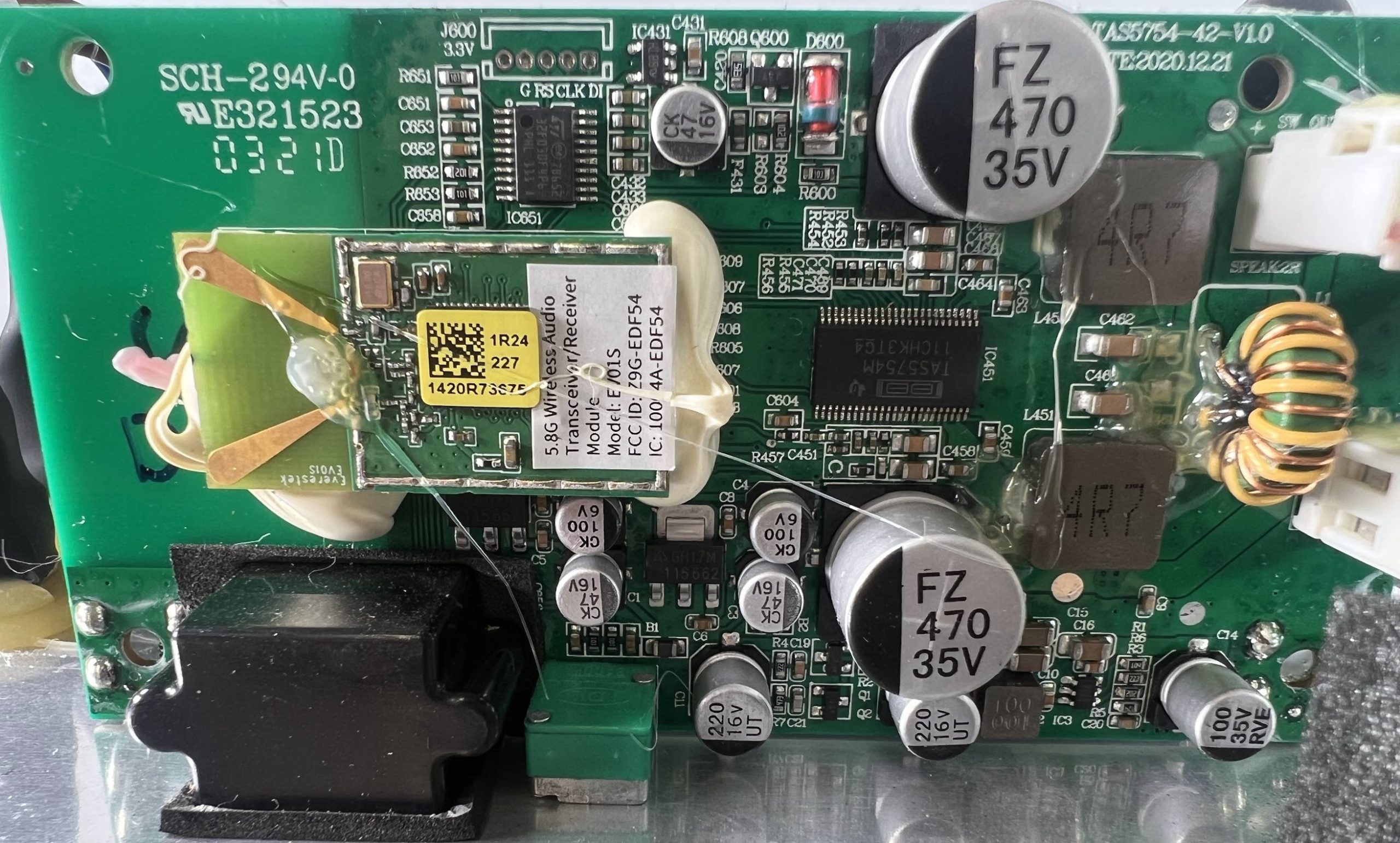
That is of course still completely sufficient for this combination and also harmonizes quite well with the two stereo satellites. But even the 50 watts output must be mastered in terms of cooling. This has to be solved by a separate heat sink on the back between the circuit board and the switching power supply. It doesn’t get really hot, at most quite warm.
Interim conclusion
Despite my technical objections and the considerably lower output power, one has to remain fair and always put everything in the right relation to the price. Offering such a system for currently less than 200 Euros is reasonable and almost something like a friendly invitation to always turn a blind eye. The price demands hard compromises and alone two decent crossovers could not have been priced in without loss. Discrete components simply cost too much, seen in relation. An active separation in the mid and high frequency channel would have required a different connection cable to the passive speaker. Unfortunately, these are also extreme cost drivers. Whereby the thin cable with RCA plug naturally also disgusts me. That is just the sheet metal standard of the audio industry for low-cost solutions.
The quality of workmanship is ok, even if I would have checked the top layer of the panels in the carpenter’s shop more meticulously. Frayed openings don’t work at all, even if the customer doesn’t see them in the end. And the amount of hot glue… Apart from the optical low point of the radio modules, covering a power amplifier chip with glue is almost an assault.


14 Antworten
Kommentar
Lade neue Kommentare
Urgestein
Urgestein
1
Veteran
Urgestein
Mitglied
Urgestein
Urgestein
Veteran
Mitglied
Mitglied
Mitglied
Mitglied
Alle Kommentare lesen unter igor´sLAB Community →