


From black, grey and selective emitters
Again, I want to keep the theory as short as possible, but I can’t spare the reader it entirely. 100 years after Herschel’s lunch eureka, Planck, Stefan, Boltzmann, Wien and Kirchhoff defined the electromagnetic spectrum more precisely, establishing qualitative and quantitative relationships to describe infrared energy. For the sake of safety, I will leave out this part of the formula in detail, but must first briefly discuss the so-called black body, which represents the ideal case, so to speak, and is in fact indispensable for understanding non-contact temperature measurement technology and its calibration.

Sectional view of a black body radiator:
1 – ceramic tube, 2 – heater, 3 – tube made of Al2O34 – orifice plate
This black body is an ideal body which absorbs all radiation falling on it and on which neither reflection nor transmission occur. It radiates the maximum possible energy for all possible radiators at each wavelength, whereby the radiance is independent of the angle. But nothing in life is really ideal and so we deal next with the grey as well as the selective emitters and thus come quite a bit closer to our goal.
The bright life along with some coffee cream
Not every body corresponds to the radiantly beautiful ideal of the black radiator with a so-called emissivity (explanation coming soon!) of 1.0 – unfortunately. If only this emissivity changes, the source is also referred to as a grey emitter. If temperature and wavelength dependence are added as modifying factors, one has a selective emitter. And this is exactly where the crux begins, if you just unpack the beautiful new infrared measurement technology and start without thinking.
Many bodies emit much less radiation at the same temperature! The emissivity ε indicates the ratio of the real radiation value and that of the black body. This value is between zero and one and must be known for the material in question.
The reflected radiation from the environment and possibly infrared radiation allowed to pass through the body we want to either ignore later in our actual measurements (since it is likely to fall within the range of measurement tolerances in these test setups) or even use specifically. Too much theory? I simply used the morning cup of coffee to symbolize this boring subject matter a little bit:
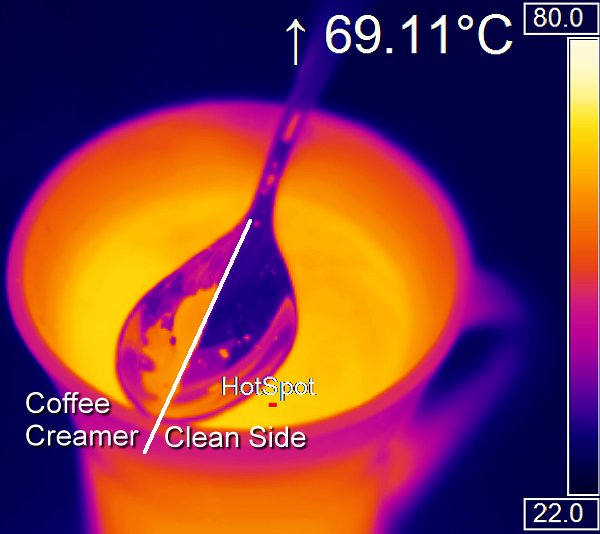
For the test setup, the freshly brewed hot coffee from my machine is placed at approx. 80 °C in a glass that has already been preheated with hot water, together with a hot stainless steel spoon and some coffee cream, in order to keep the respective temperature differences as low as possible and to prevent the coffee from cooling down too quickly. I still wait a few minutes until the coffee, glass and spoon are about the same temperature. Then I take out the spoon, wipe one half lengthwise with the kitchen towel, and the above infrared image emerges.
Different surfaces are the death of every standup measurement
Every surface (different materials and structures) has a certain emissivity, which must first be known in order to be able to measure anything accurately at all. Better handhelds can be calibrated manually or you can use a suitable software of the manufacturer. Unfortunately, a value of 1.0 is almost always preset by default, which is never or only very rarely encountered in reality. Thus, at least all measurements in which the emissivity was set to 1.0 can be confidently chalked up to expensive entertainment that is of no use to anyone. Because:
Without prior input or indication of the respective emissivity of a measuring point, any measurement carried out is completely worthless!
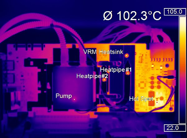
A nice example of this is the following shot. The different colors actually visually recreate the temperature curve, but what happened to the heatpipe and VRM heatsink? Although they are extremely hot, they appear rather dark and thus cold in the picture! Only by applying our special varnish from the “poison cupboard” (orange measuring points) usable measuring results are obtained”. Of course, one could also store the emissivity of the copper composite material and the aluminium for each of the measuring points, but would then encounter the problem that these emissivities in particular change strongly with increasing temperatures.
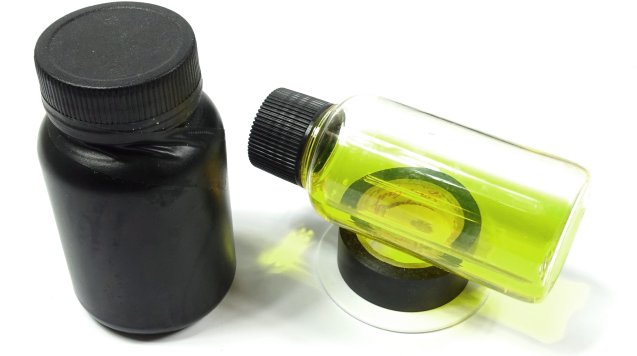
Therefore, we use a very temperature-resistant, somewhat matt clearcoat, whose emissivity is known to us and remains almost constant over the entire temperature range. Such special and unfortunately also very expensive lacquers are used by the industry to protect electrical components and even entire circuit boards from environmental influences such as high humidity. One speaks therefore also colloquially of a tropicalization. Unfortunately, you won’t find such lacquers in normal shops, especially as they have to be tested (or had tested) for our purpose in elaborate series of measurements beforehand.
However, for heatpipes (GPU, CPU coolers) up to 100 °C, we can even use a cheap black insulating tape in an emergency, but its emissivity must first be determined. Matte black measuring tape is thinner and has a much higher emissivity above 0.97, but it doesn’t have to be that expensive for the small test here. Let’s just take a look at the picture of our next test setup, where we see a hot heat pipe and the cheap tape.
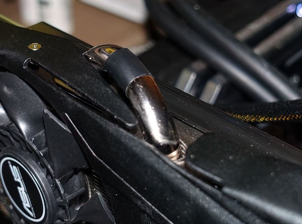
While the measurement of the approx. 80 °C hot heatpipe with the factory default of 1.0 fails grandiosely, both the measurement with the previously measured tape (0.656) and the measurement with the correctly entered emissivity (0.12) for the material at 80 °C are correct. Unfortunately, the latter changes over the occurring temperature spectrum by a factor of three and is thus completely useless with possible temperature fluctuations. Metallic surfaces whose temperature changes can therefore not be measured in a meaningful way!

The varnish is ready: We measure pins correctly
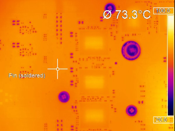
It is important, not only for high-resolution cameras, that no disturbing temperature differences due to different emissivities are recorded in the measuring range, as they have a negative influence on the output mean value. The next two illustrations show how extreme something like this can be. First, we measure a VRM pin (which is very hot in itself), which gives off heat directly to the copper traces and thus to the immediate vicinity of the PCB. Nevertheless, due to the much lower emissivity of the solder joint, without correction for our measurement with the (incorrectly) read approx. 50 °C, this area is first a kind of cold spot.
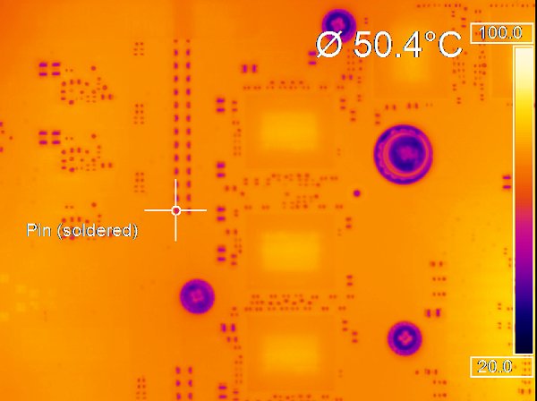
Now we simply paint a part of the pins and notice that suddenly the entire surface has the known emissivity that we can use and the camera can no longer optically detect the painted pins as such. A difference of 23 °C between the two measurements at the identical measuring point is an order of magnitude that can decide whether such a measurement is successful or not!
Thus, without the most mundane basic knowledge of measurement technology as well as the necessary basic requirements for the measurement setup and procedure, much too low measurement results are almost always the regrettable rule.


43 Antworten
Kommentar
Lade neue Kommentare
Urgestein
Veteran
Urgestein
Urgestein
1
Veteran
Urgestein
Mitglied
Urgestein
Urgestein
1
Urgestein
1
Urgestein
Urgestein
Urgestein
Mitglied
Mitglied
Urgestein
Alle Kommentare lesen unter igor´sLAB Community →