


I briefly tested the whole thing in the PC with the GPU-Z tool. Unfortunately, the hotspot problem was still there. Annoying. The GPU had slightly better temperature values, but the hotspot temperature went up to 105 °C again. More is not possible. In addition, despite the hotspot problem, I ran the GPGPU benchmark from AIDA64 and noticed that the card suddenly stopped producing an image during the “single-precision flops” test. The GPU didn’t seem to work quite as stable here either. I didn’t take a picture of the black screen, just imagine a black placeholder.
After that, I just switched the computer off and on again to check whether the image came back at all. As the image worked again when I restarted it, I was fine for the time being. So nothing had worked and the card was then disassembled again.
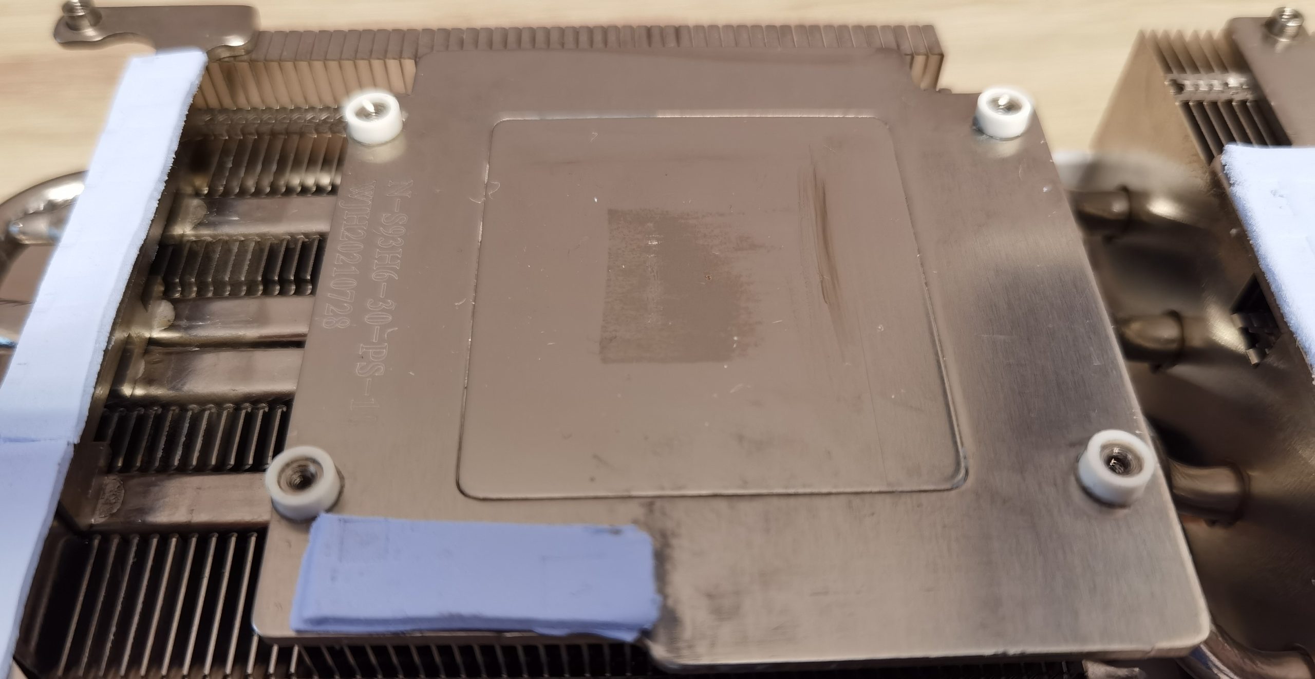
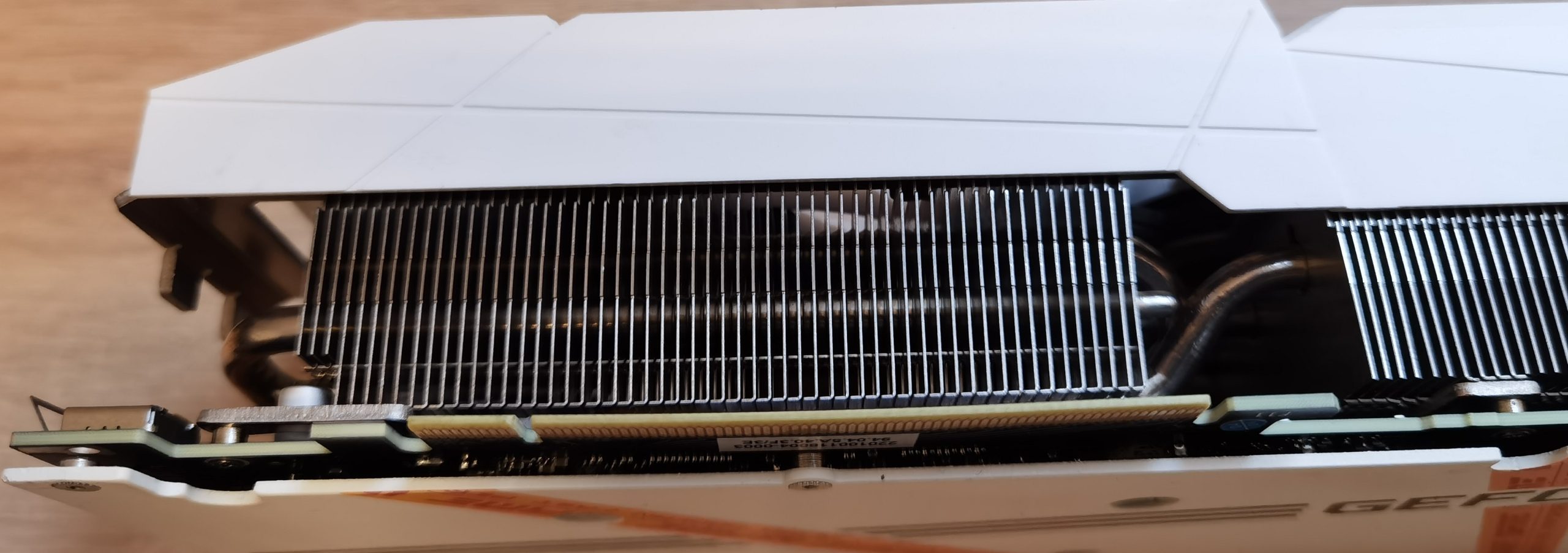
 You can see from the imprint of the graph pad on the heat sink that the GPU on the right-hand side wasn’t positioned correctly. Annoying.
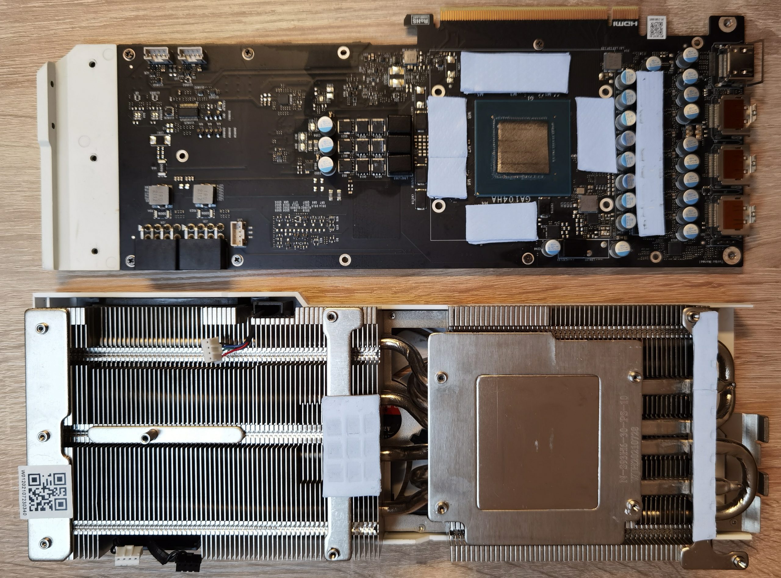
To find the problem, I looked at the board on the right-hand side from the GPU. There are three memory modules installed on this side and the mounting holes are also quite far to the right. This gave rise to the suspicion that the thermal pad might not give way as well as planned or that the board might sag a little more on the right-hand side of the GPU. Unfortunately, you can’t really see this with the pads fitted.
Since white spacer rings were still attached to the heat sink, which were only 0.4 mm narrower than the total height of the GPU, it could also be that the contact pressure of the board was not sufficient to press the GPU straight against the heat sink. To take a closer look at this on the GPU, I did a little experiment and boldly removed the spacer rings to see what would happen if they were no longer there. Then I reassembled the graphics card, without the screws of course.
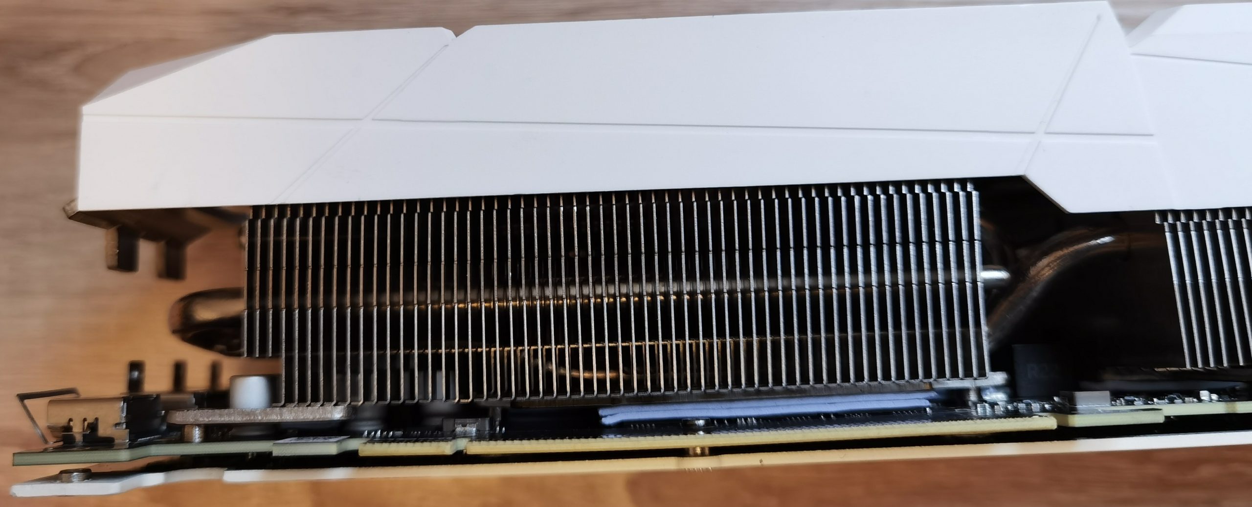
Then I screwed the screws back in slowly and evenly, alternating them, and at a certain point I noticed something interesting on the board. You need to know that the rigid backplate is screwed to the board at nine fixing points and then five more fixing points are screwed to the heat sink further away. Without the spacer rings, the PCB is then pulled in two directions, i.e. once towards the backplate and once towards the heat sink. To illustrate this better, I exaggerated the tightening slightly, but only enough to ensure that the board or components were not damaged. Here you can see how the board is slowly bending.
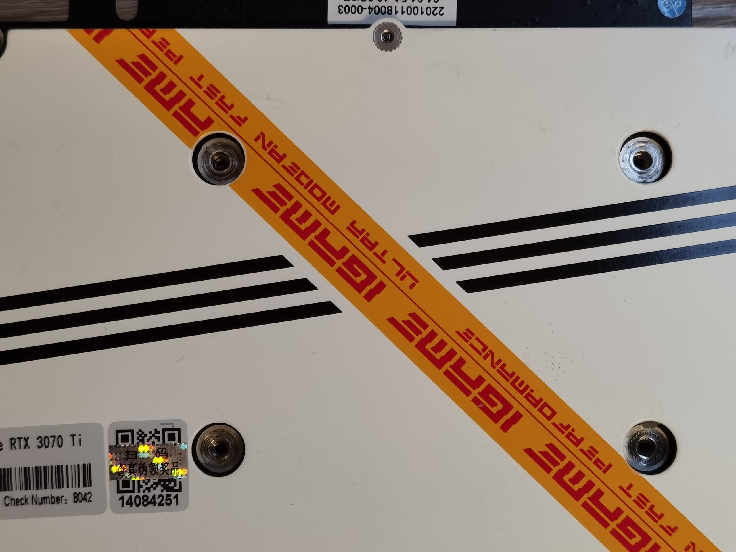
In the next pictures you can even see from the outside how the PCI connector is bending slightly. It would have been impossible to simply push it back into the PCIe slot.
After this experiment, a new solution had to be found without bending the board and where pressure is best exerted directly on the GPU from below and then distributed from there to the other mounting points via the other thermal pads.


42 Antworten
Kommentar
Lade neue Kommentare
Mitglied
Veteran
Urgestein
Urgestein
Urgestein
Urgestein
Urgestein
Urgestein
Urgestein
Urgestein
Urgestein
Urgestein
Urgestein
Urgestein
Urgestein
Urgestein
Urgestein
Urgestein
Urgestein
Alle Kommentare lesen unter igor´sLAB Community →