


What is actually already being read out and displayed?
Let’s look at the already known module first. As an example, I have marked two places where temperature sensors really exist, even if one has to make further restrictions here. It concerns on the one hand the SPD hub and on the other hand the PMIC, which also takes over the voltage regulation. With less than 5 watts of power dissipation in OC mode, one bar is certainly not yet a thermal time bomb, but 2 bars already reaches up to 10 watts. If you have all banks full, that’s up to 20 watts just for the RAM. Hallelujah.
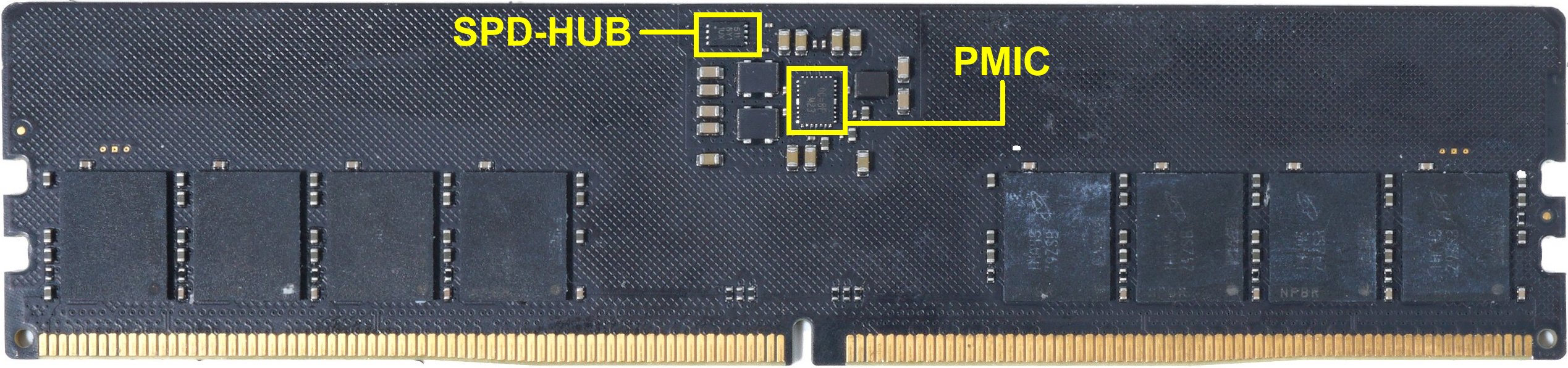
The SPD hub as a basis for a possible rule of thumb
The IC for the SPD hub contains an (analog) sensor which returns readable decimal values and which also works quite accurately. In the JEDEC specifications, which are unfortunately hidden behind a paywall and for which you have to pay a lot, you will also find the temperature limits for this SPD hub. Since the IC itself produces hardly any power dissipation, but sticks directly to the PCB, the IC is a good indicator for the temperature of the entire PCB, which after about 30 minutes of full load has also warmed up in a fairly balanced way. Hotspots dissolve into averages over time, after all.
| High limit | 55 °C |
| Critical limit | 85 °C |
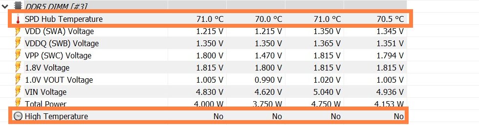
Despite OC and some tests with up to 1.4 volts in the “benchmark mode” of the OCPC Extreme, I did not succeed in bringing this value to the critical limit. With readout values of slightly over 70 °C at 1.35 volts and a maximum of 75 °C at 1.4 volts, the critical limit will therefore not be reached. So I can give the all-clear, everything remains in the green area.
But what can you use the value for the SPD hub for now? Since the individual memory modules also have a thermal effect on the circuit board, the SPD value can also be indirectly inferred from the memory after a longer period of heating! We will see later that here, depending on the make, there is a temperature difference of between 10 and 13 degrees between the SPD value and the hottest point on the surface of the memory module. What that means for the interior, we will clarify in a moment. But it is at least a rough indication and also a useful guideline for a possible rule of thumb.
The temperature values of the PMIC
The PMIC temperature is not a true sensor value, but again just a collection of flags that only very roughly outline the temperature ranges. Since hardly any power is dissipated in the IC itself and thus hardly any waste heat is generated, we can actually ignore this value calculation completely. You can find the flag in HWINFO under the messages for the respective RAM module as “High Temperature” (see picture above). For the sake of completeness, I have also listed the flags and the corresponding temperature ranges:
| 000 | < 85 °C |
| 001 | 85 °C |
| 010 | 95 °C |
| 011 | 105 °C |
| 100 | 115 °C |
| 101 | 125 °C |
| 110 | 135 °C |
| 111 | > 140 °C |
So we can completely skip the PMIC, unlike the SPD hub, because the value is of no use to us. Before a critical flag appears here, the memory modules have long since burned up. On the next page we will see how warm or even hot it all really gets.


20 Antworten
Kommentar
Lade neue Kommentare
Veteran
1
Mitglied
1
Urgestein
Veteran
Urgestein
1
Urgestein
Urgestein
1
Urgestein
Mitglied
Mitglied
1
Mitglied
Urgestein
Urgestein
Urgestein
Alle Kommentare lesen unter igor´sLAB Community →